
Implementation Report – Part 2

- rurmus project -
24 – Positioning the water wheel using a crane
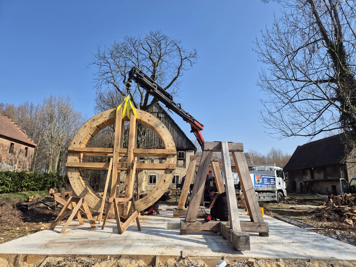
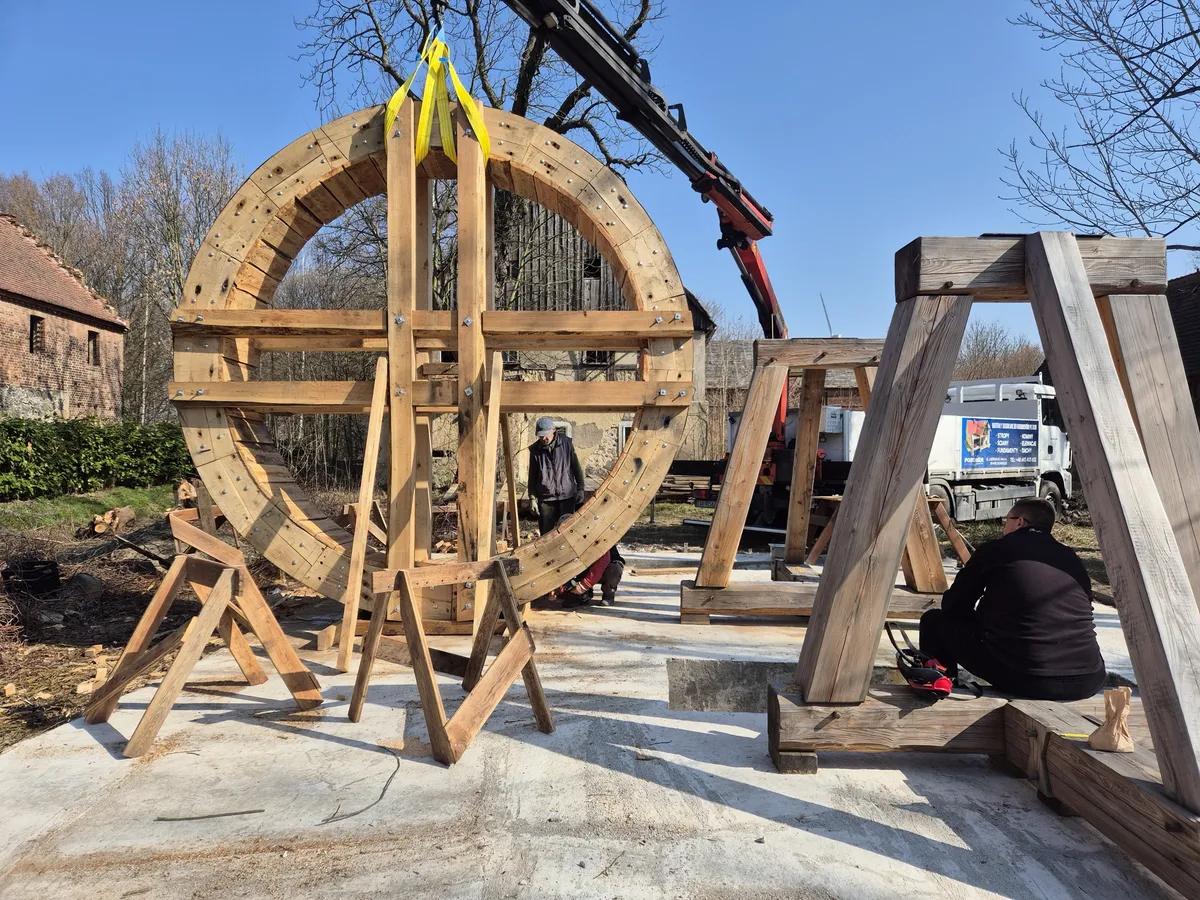
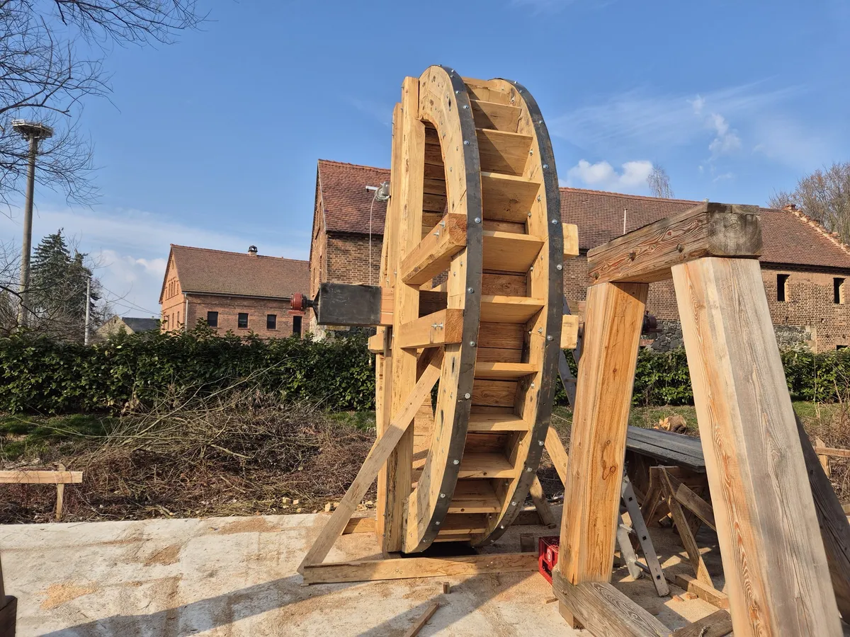
Once the water wheel and its supports were prepared, the positioning of the device’s largest component at the installation site began. The photos show the wheel suspended by straps from a mobile crane boom, as well as the support structure and the workers present during the operation. Due to the wheel’s large size, mechanical equipment was required to lift and maneuver it.
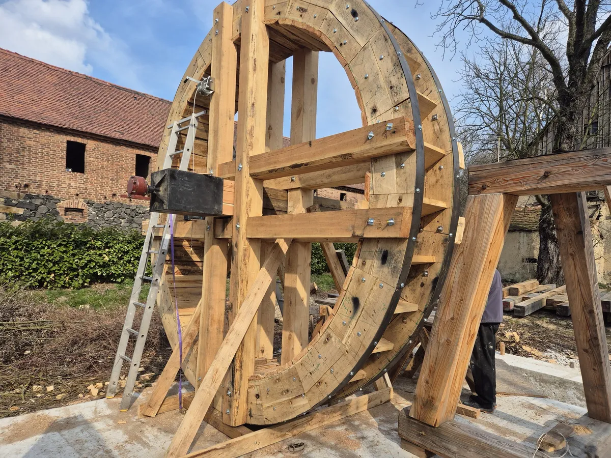
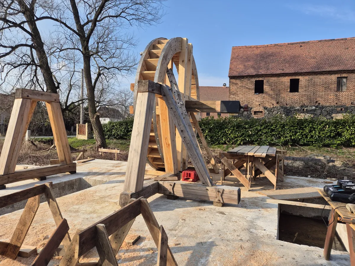
Subsequent shots show the wheel positioned vertically next to the wooden supports and the preparation of its mounting point. The documentation illustrates the transition from the separately prepared component to its installation within the final assembly. The photos depict the handling of the wheel and the positioning of the structure; they do not yet show the drive system in operation or water flowing through the unit.
The gallery includes both shots of the crane during the lifting process and views of the wheel positioned alongside the supports.
- rurmus project -
25 – Assembly of the wooden tower and upper structure
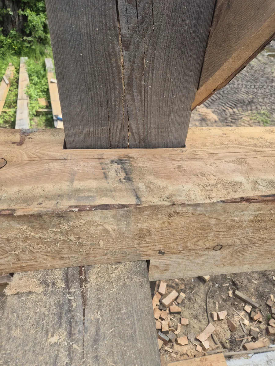
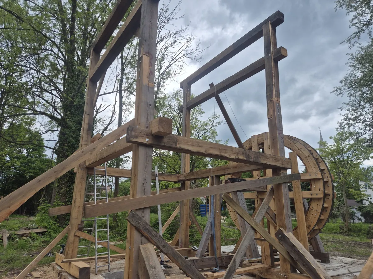
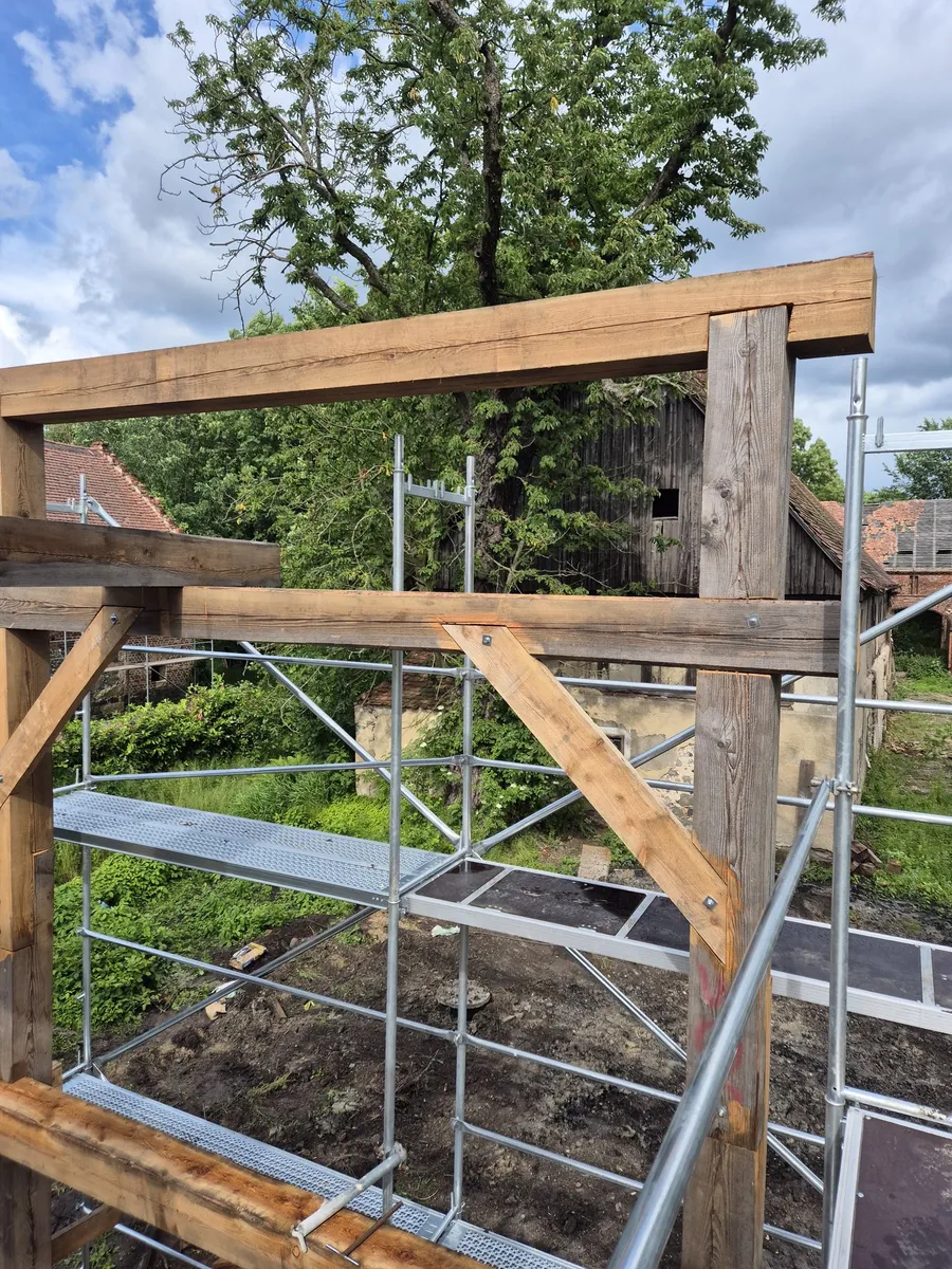
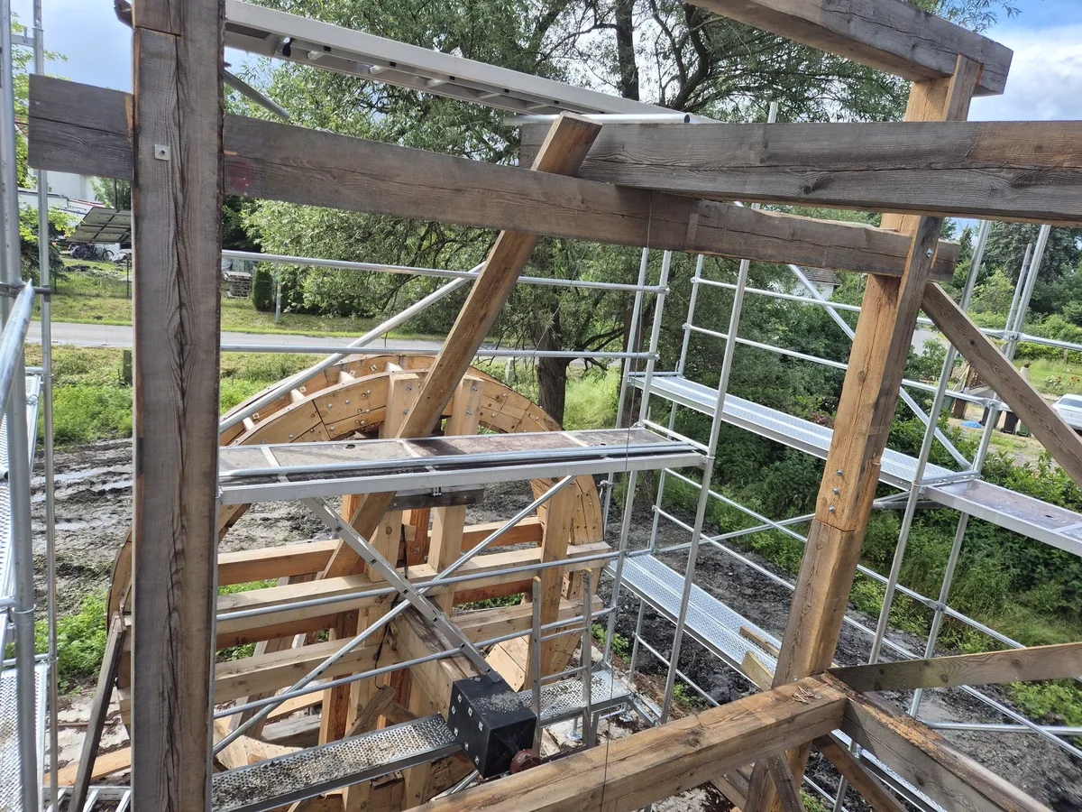
The next stage involved assembling the load-bearing framework of the Rurmus. The photos show the massive posts, horizontal beams, and diagonal braces that form the three-dimensional structure surrounding the water wheel. A close-up reveals the joint between a post and a beam, while wider shots show the arrangement of components throughout the entire machine.
Beams and working platforms were constructed in the upper section to support the mounting of subsequent mechanism assemblies. The scaffolding visible in the photographs provided access to assembly points located high above the ground. The collected images document the gradual erection of the tower, the method of supporting the upper section, and the relationship between the load-bearing structure and the previously installed water wheel.
Combining detailed carpentry shots with wider views allows for a comparison between an individual structural joint and the tower’s framework as a whole.
- rurmus project -
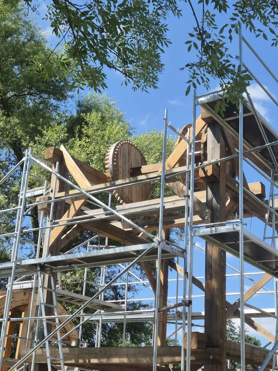
26 – Fabrication and assembly of the large gear wheel
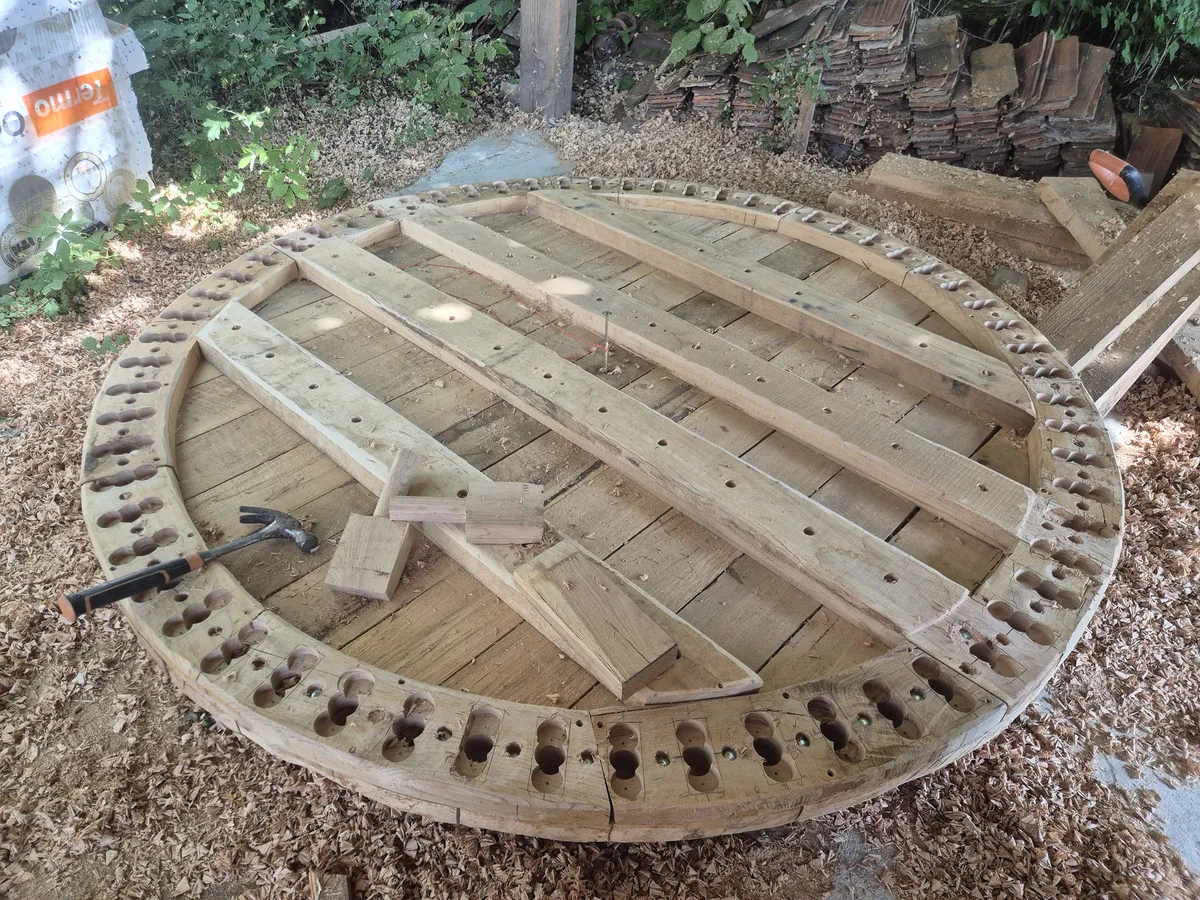
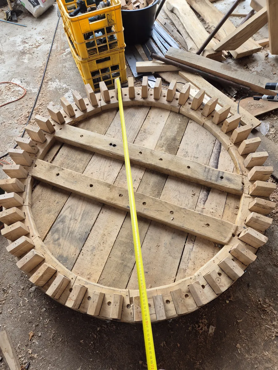
Photos from this stage show the large wooden gear wheel at various phases of its construction. Visible are its outer rim, the arrangement of the wooden teeth, and the components forming the wheel’s center. A shot taken during the machining process reveals that the individual parts were fabricated separately before being assembled into a single gear unit.
Subsequent photographs show the finished wheel and its installation onto the Rurmus structure. This component transmits motion from the waterwheel’s axle to the rest of the mechanism. Comparing the workshop photos with the installation shot allows one to trace the process from the preparation of the wooden parts to the placement of the gear within the device, without attributing operational tests to the photos that do not depict them.
The gallery includes views of the entire wheel as well as a close-up showing how the wooden teeth were crafted.
- rurmus project -
27 – The lantern gear and the interaction of transmission components
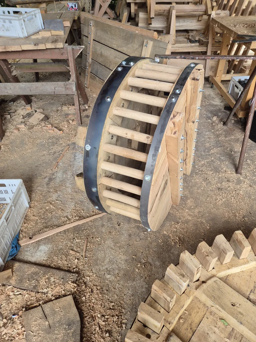
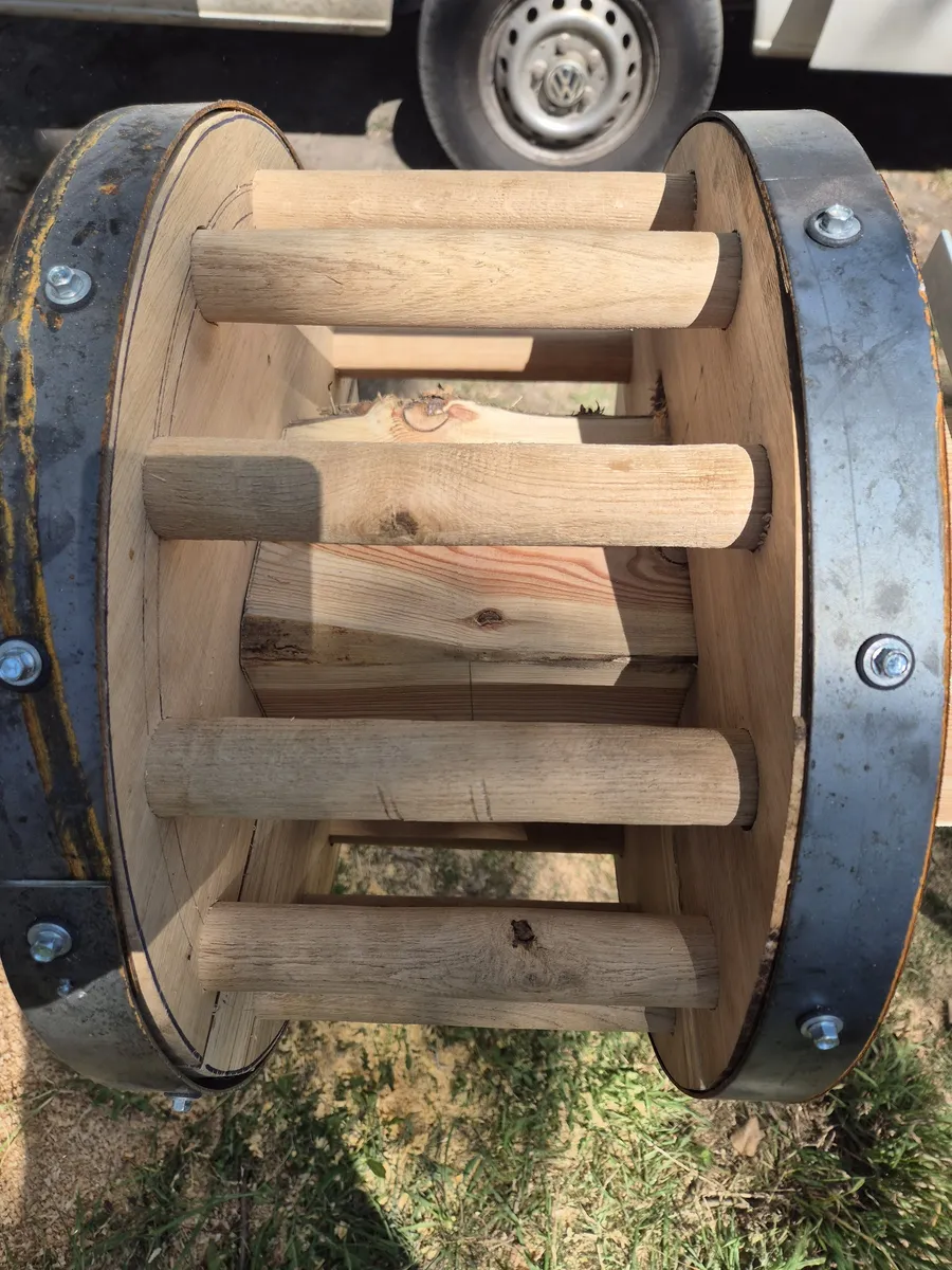
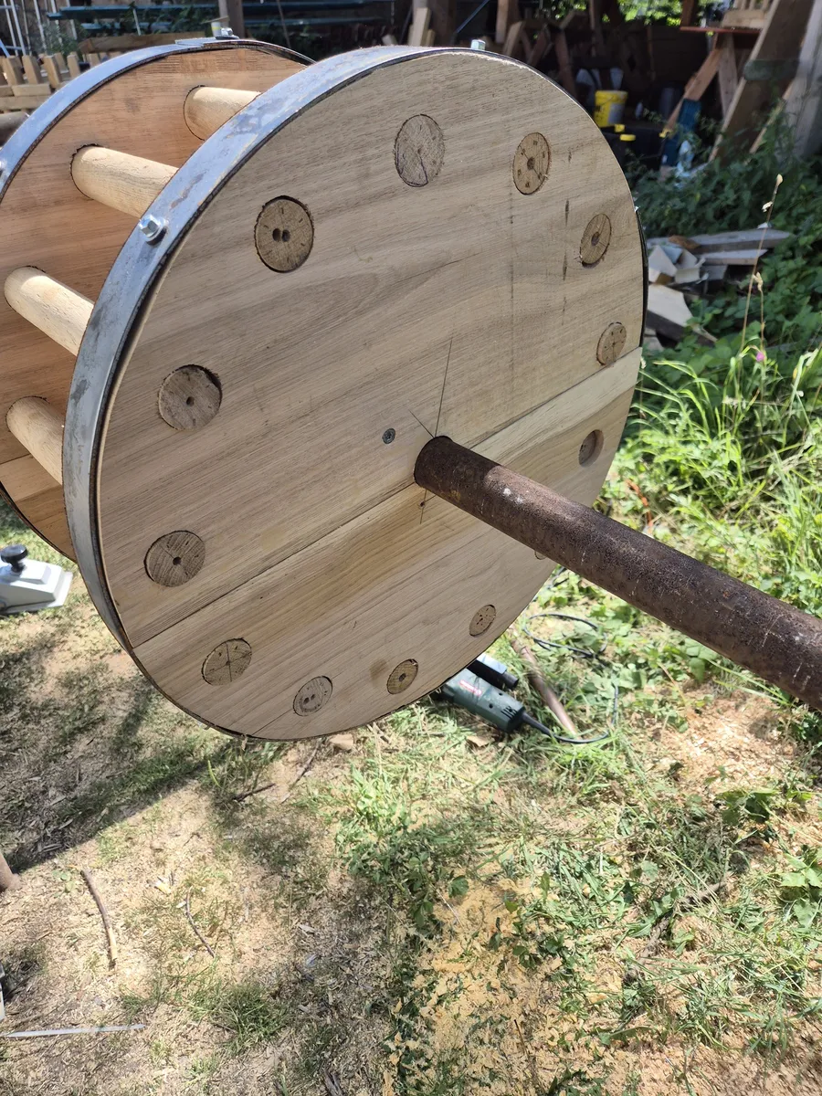
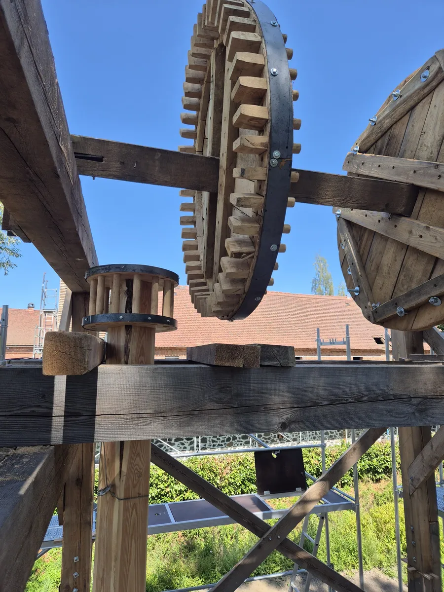
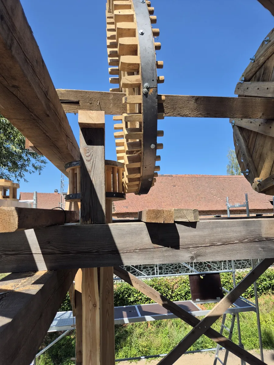
This section of the documentation presents a smaller transmission component—known as a lantern gear—and its connection to the large gear wheel. Close-up views reveal the wooden staves (or pins) fitted into the lantern’s side discs. Separate shots show the two components after installation within the structure, including the point where the large gear’s wooden teeth engage with the lantern’s staves.
The photographs allow one to trace the assembly of the drive mechanism, from the finished individual component to the arrangement of parts in their operational setting. They illustrate both the materials used and the relative positioning of the components. However, the visible interface between the parts does not reveal information regarding speed, durability, or performance during water-powered operation.
A combination of detailed and wide-angle shots helps identify which transmission parts form a mating pair.
- rurmus project -
28 – Installation of the vertical drive
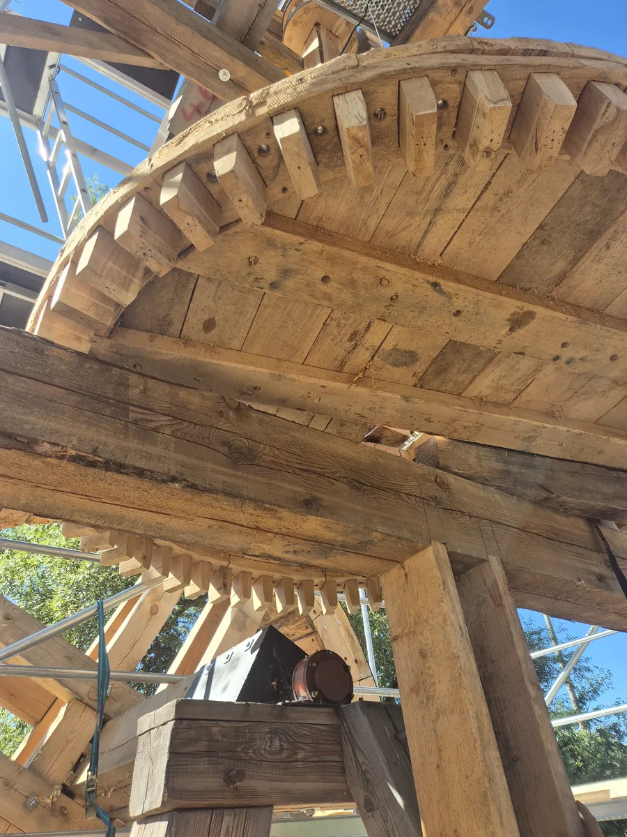
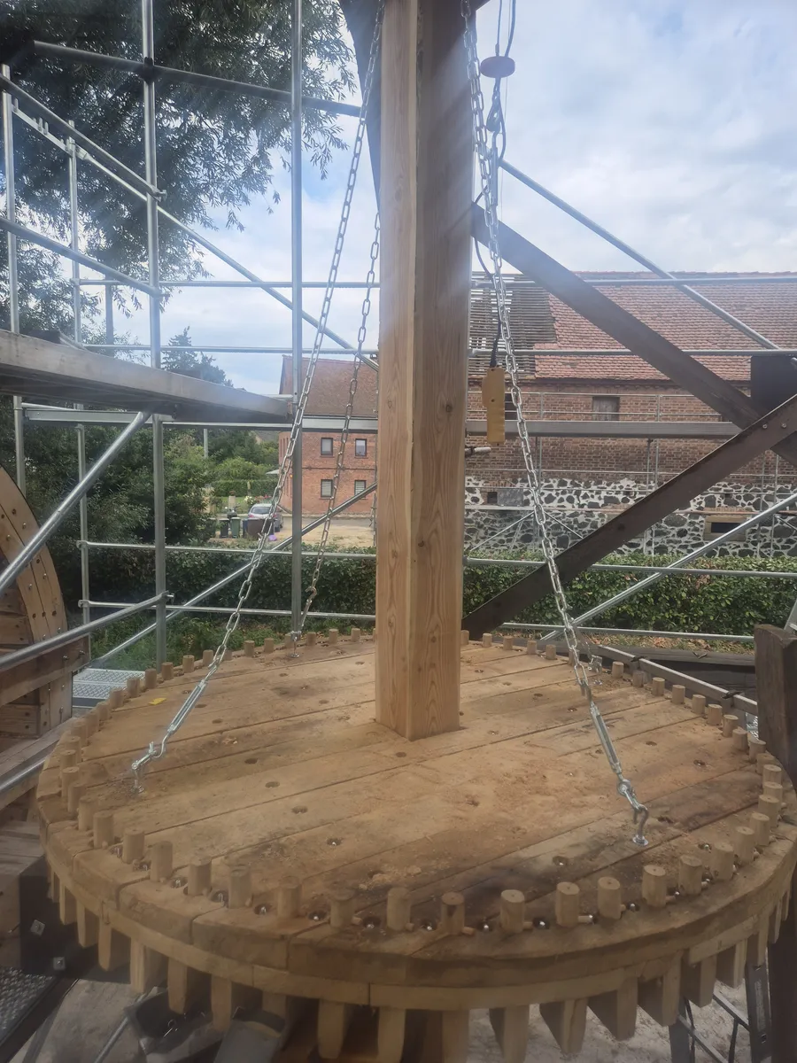
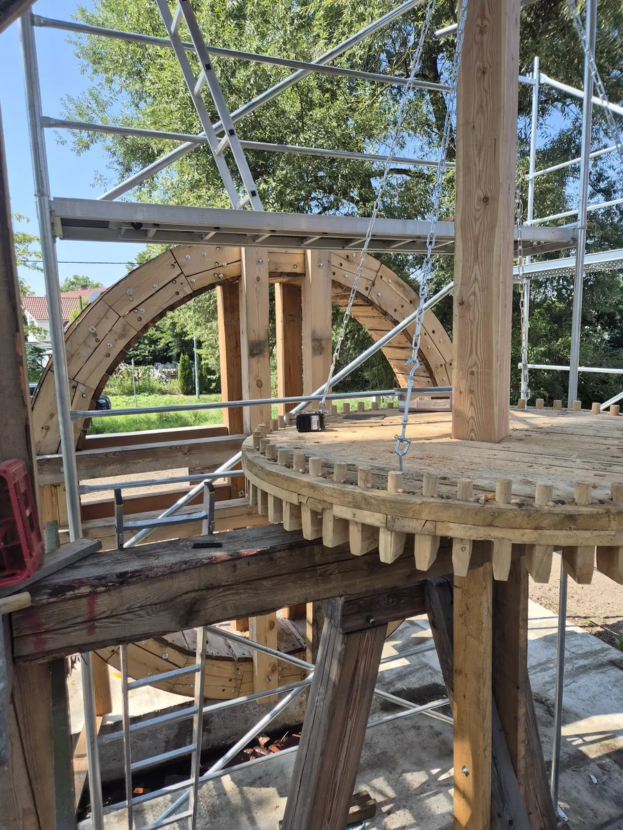
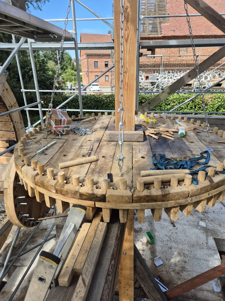
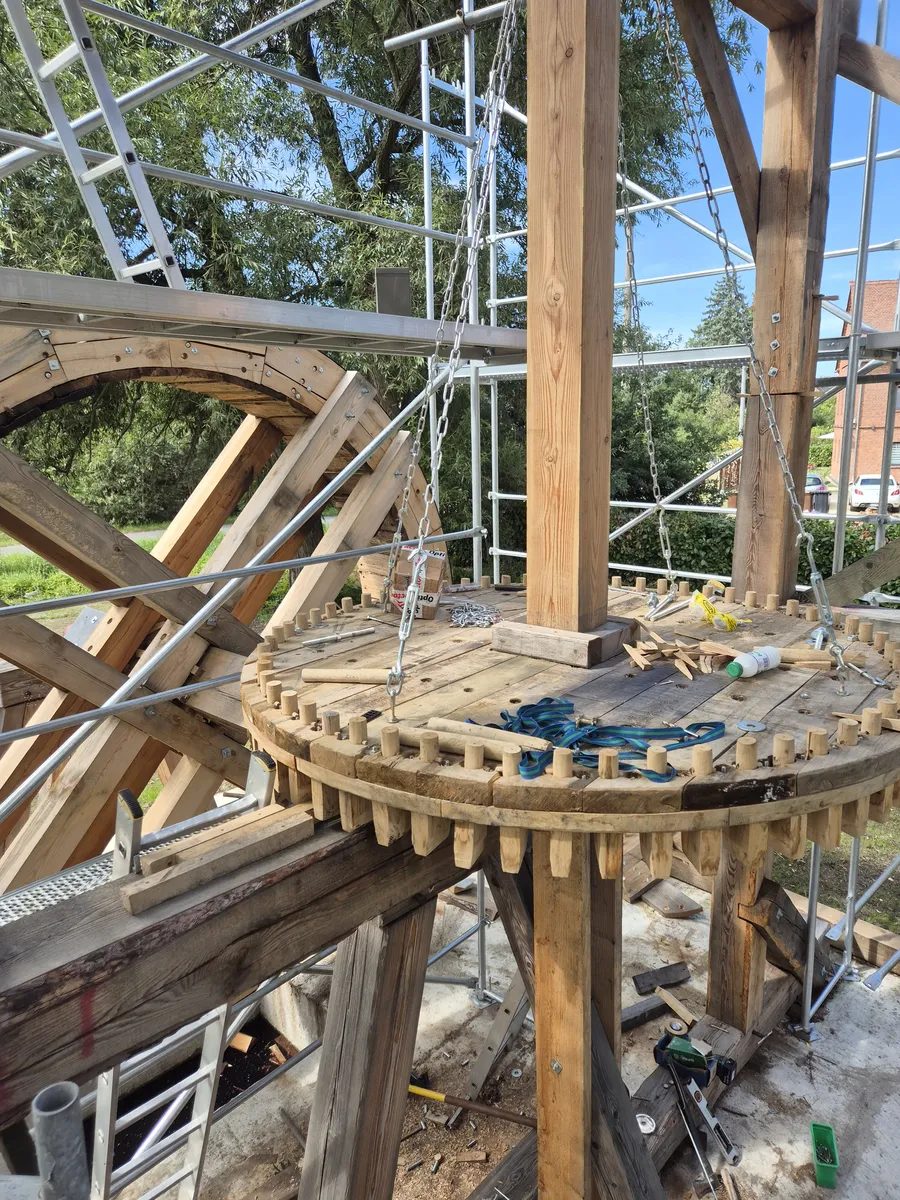
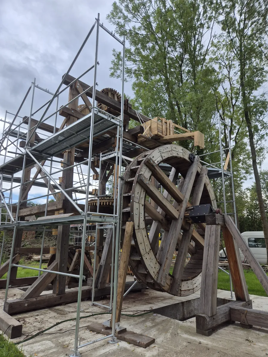
Once the gearbox was installed, the assembly responsible for transmitting motion to the bucket system took shape. The photographs show the vertical shaft at various stages of assembly, its connection to the large gear, and the lower-positioned wheel designed to drive the bucket system. Shots taken from below and from the level of the scaffolding reveal how these components are arranged within the wooden tower.
The relative positioning of the shafts and gears is crucial here: the mechanism is designed to transmit rotation from the upper part of the structure to the water-lifting assembly. Close-ups document the construction and mounting of individual parts, while photographs of the entire assembly show its placement within the machine. The photos do not constitute a record of a functional test.
A view of the connection at the top of the tower is juxtaposed with shots of the lower-mounted components of the bucket drive.
- rurmus project -
29 – Buckets, chain, and water-lifting path
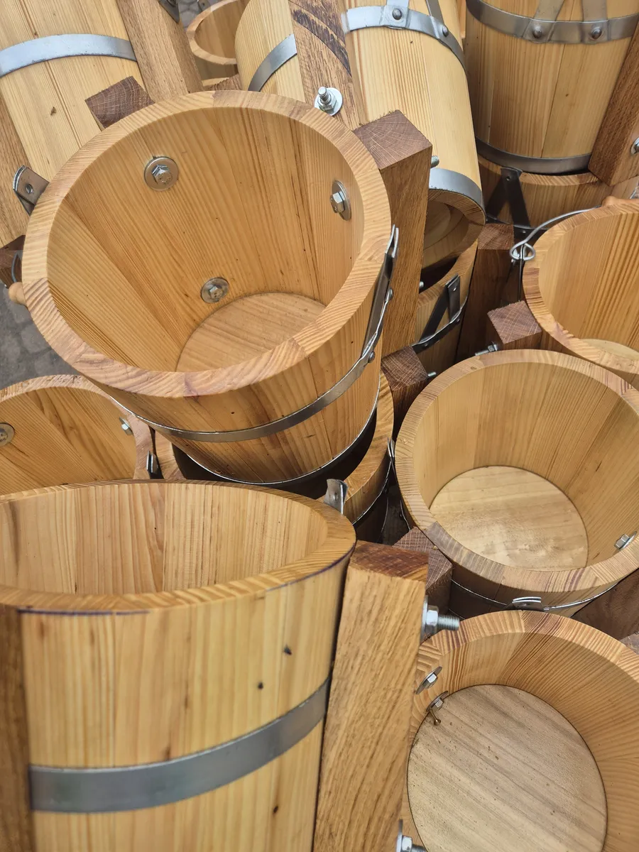
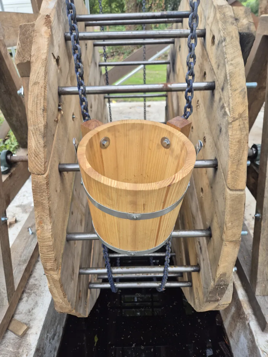
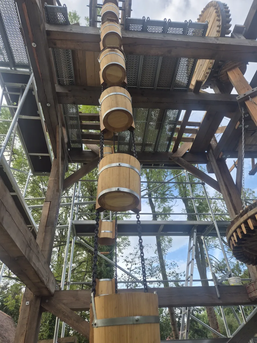
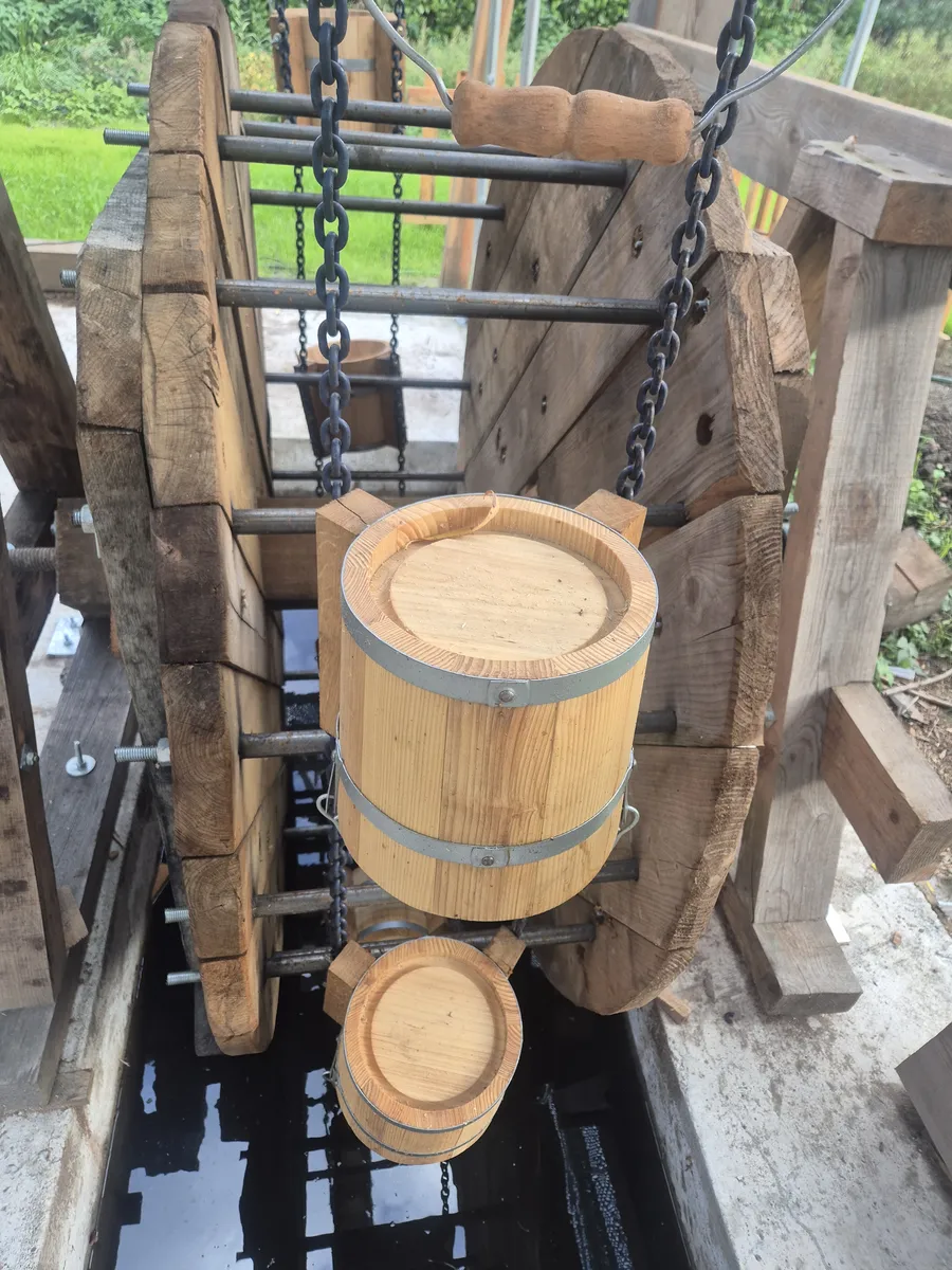
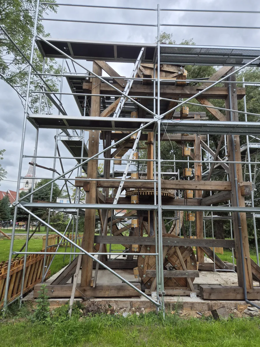
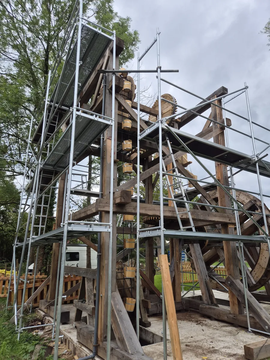
The photographs show wooden buckets prepared for installation, as well as buckets attached to the lifting system’s chain. Visible elements include two guide wheels, metal rods connecting their wooden discs, the bucket mounts, and the lower section of the device featuring the water channel. A shot taken from below reveals the chain and buckets traversing several levels of the structure.
The system’s function is to collect water at the bottom and transport it upwards. While the photographs document the construction and the path taken by the buckets, they do not provide a continuous view of the device in operation or the actual transfer of water. Documenting this process would require a separate recording showing the full operating cycle, from the lower channel to the upper discharge point.
Close-ups reveal how the wooden vessels are attached to the chain, while a shot from below shows their movement through the tower.
- rurmus project -
30 – The water-lifting mechanism after the assembly of major components
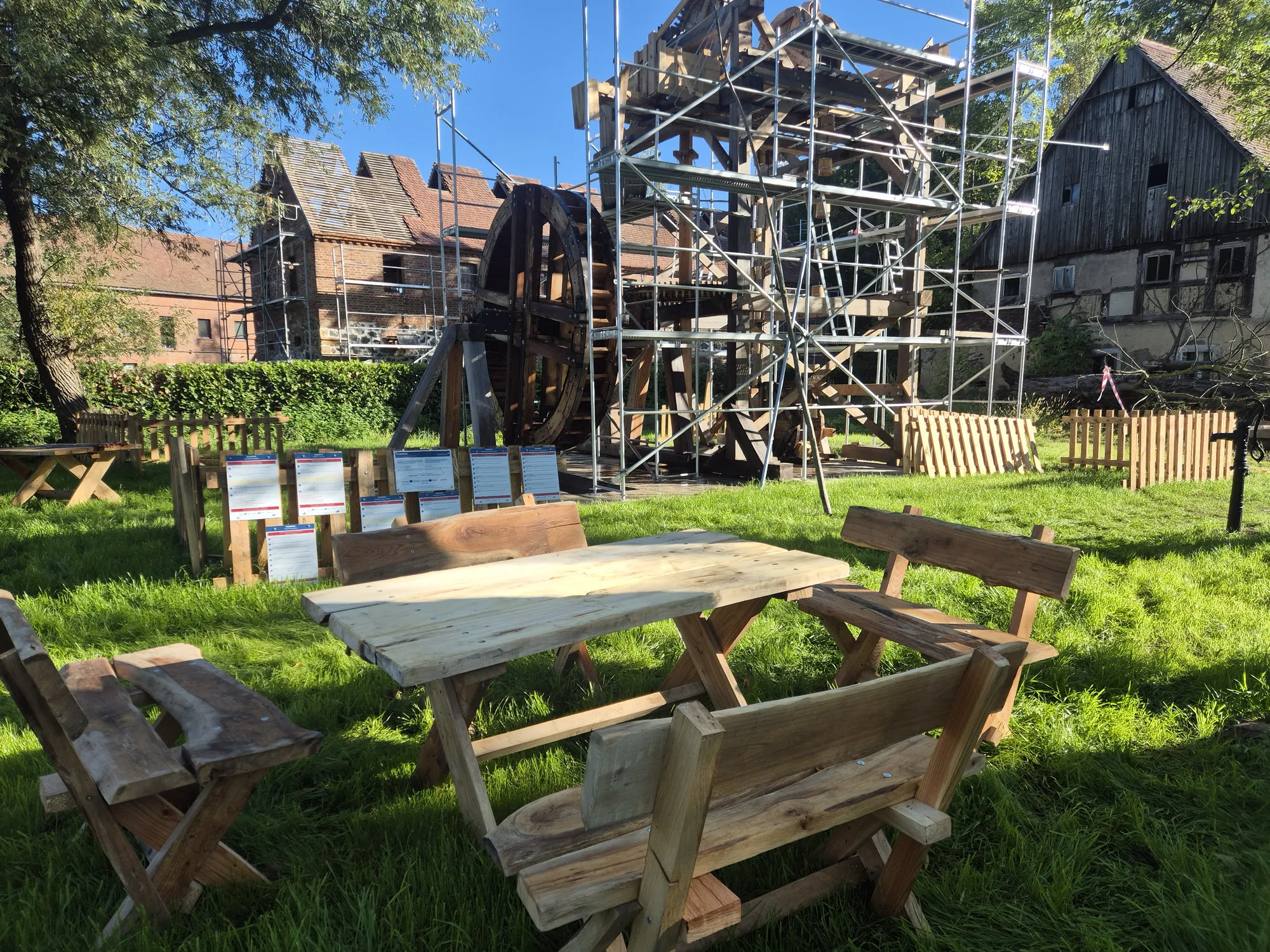
- Education - Folklore - Culture -
Contact us—we have the knowledge, experience, and international connections.
Together, we will develop and implement your idea.