
Implementation Report – Part 1

- rurmus project -
The *Rurmus* was built as a modern interpretation of historic water-handling structures, respecting the traditional carpentry techniques employed by the builders of mills, sawmills, and water-lifting devices. A key objective of the project was to showcase the craftsmanship of past carpenters and the methods used for centuries to erect large timber structures with minimal reliance on metal components.
A significant portion of the structure utilizes traditional carpentry joints—such as mortise-and-tenon, lap joints, dovetails, and wooden pegs. For centuries, these techniques enabled the construction of durable, functional structures without the need for modern fasteners.
However, it is important to note that historic structures were built in an era when safety standards differed significantly from today’s. A modern structure intended for public visitation must comply with rigorous technical and safety regulations.
Consequently, additional bolted reinforcements and safety elements have been incorporated at specific points designated by the designer. Their purpose is not to replace traditional carpentry joints, but rather to enhance user safety and ensure the structure’s long-term durability.
This approach made it possible to preserve the structure’s historic character while simultaneously meeting modern public safety requirements.
- rurmus project -
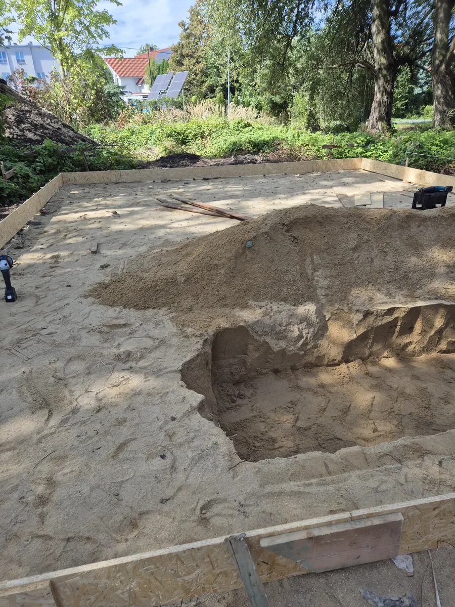
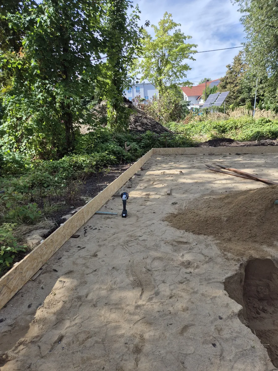
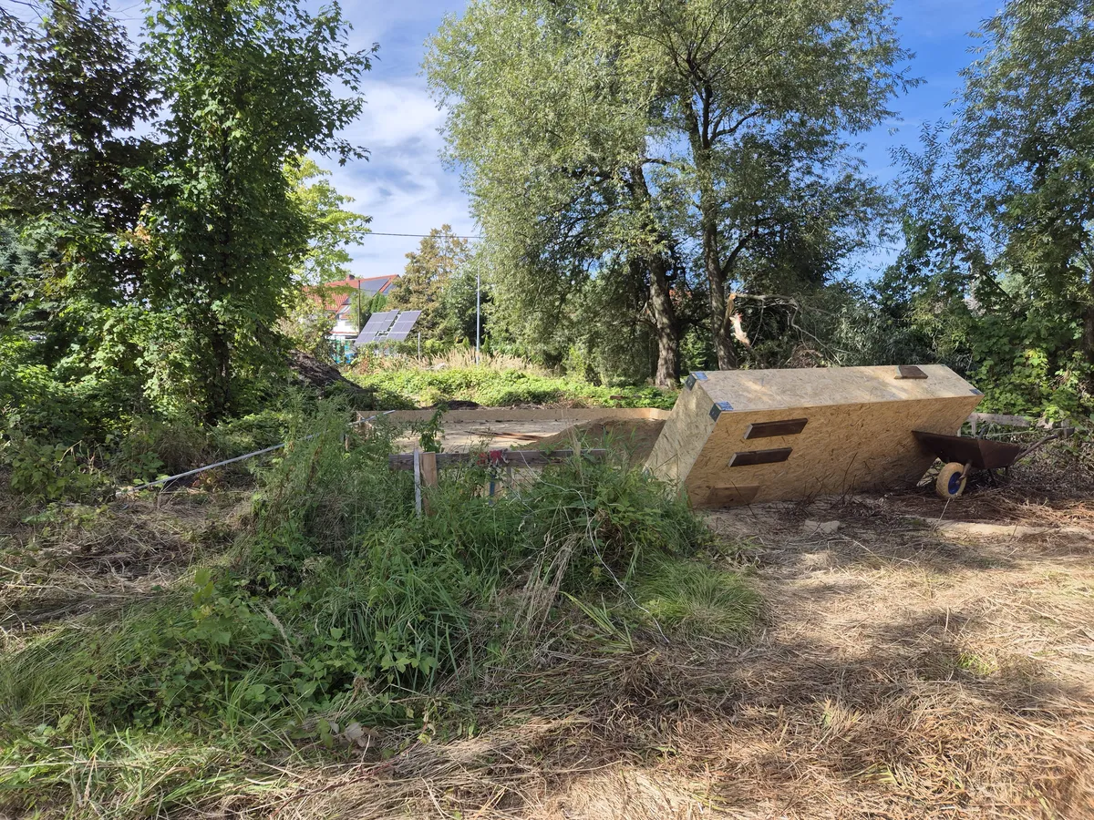
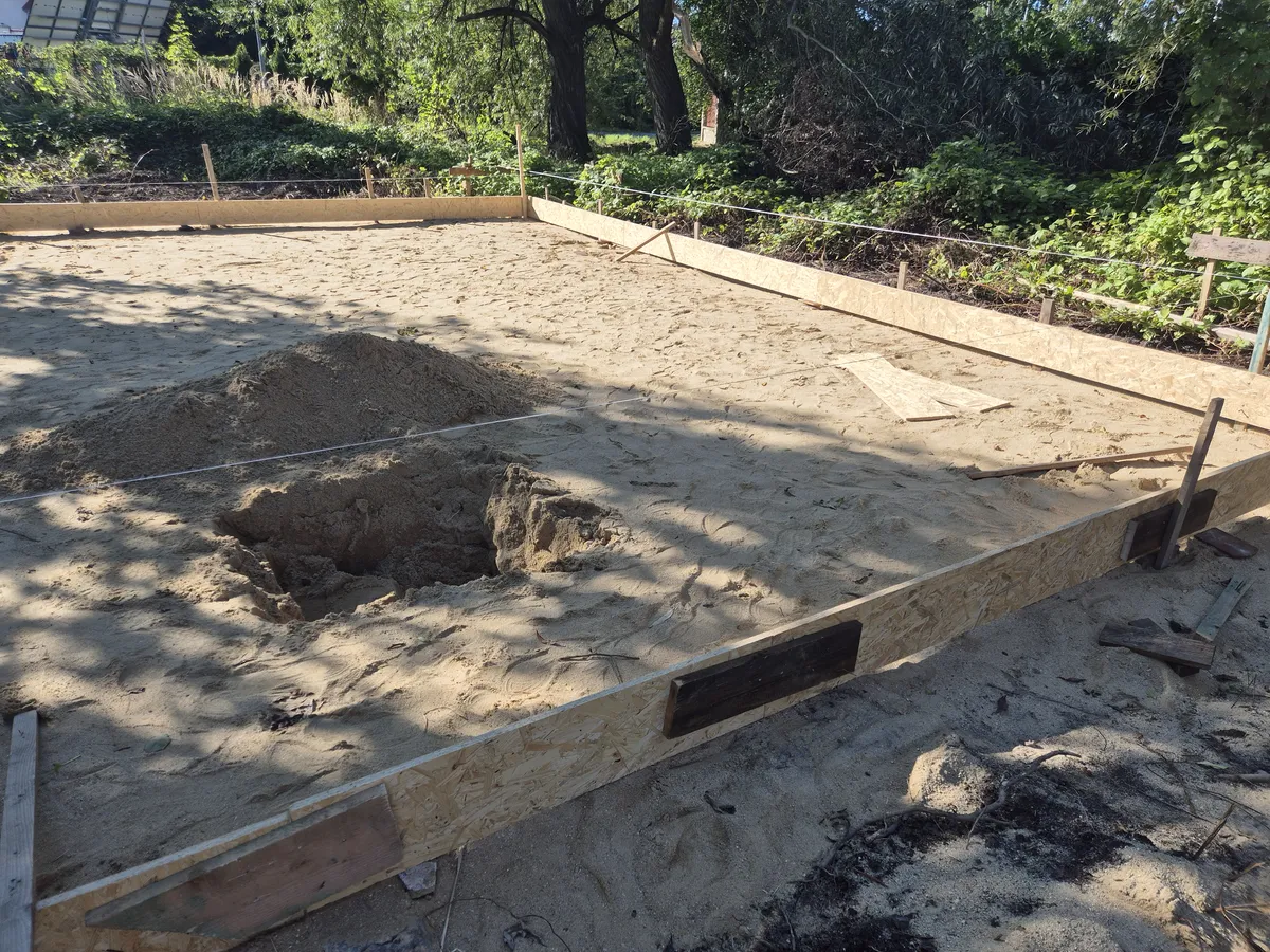
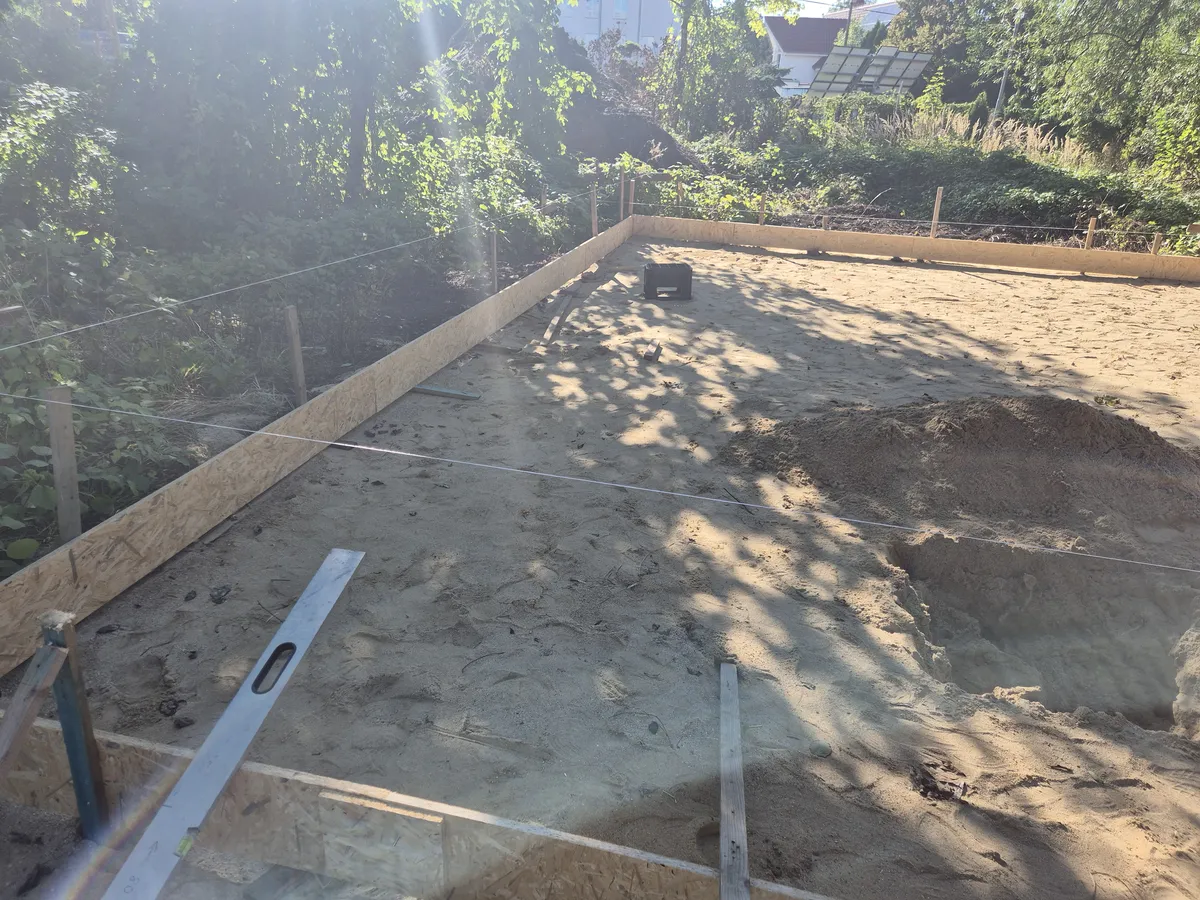
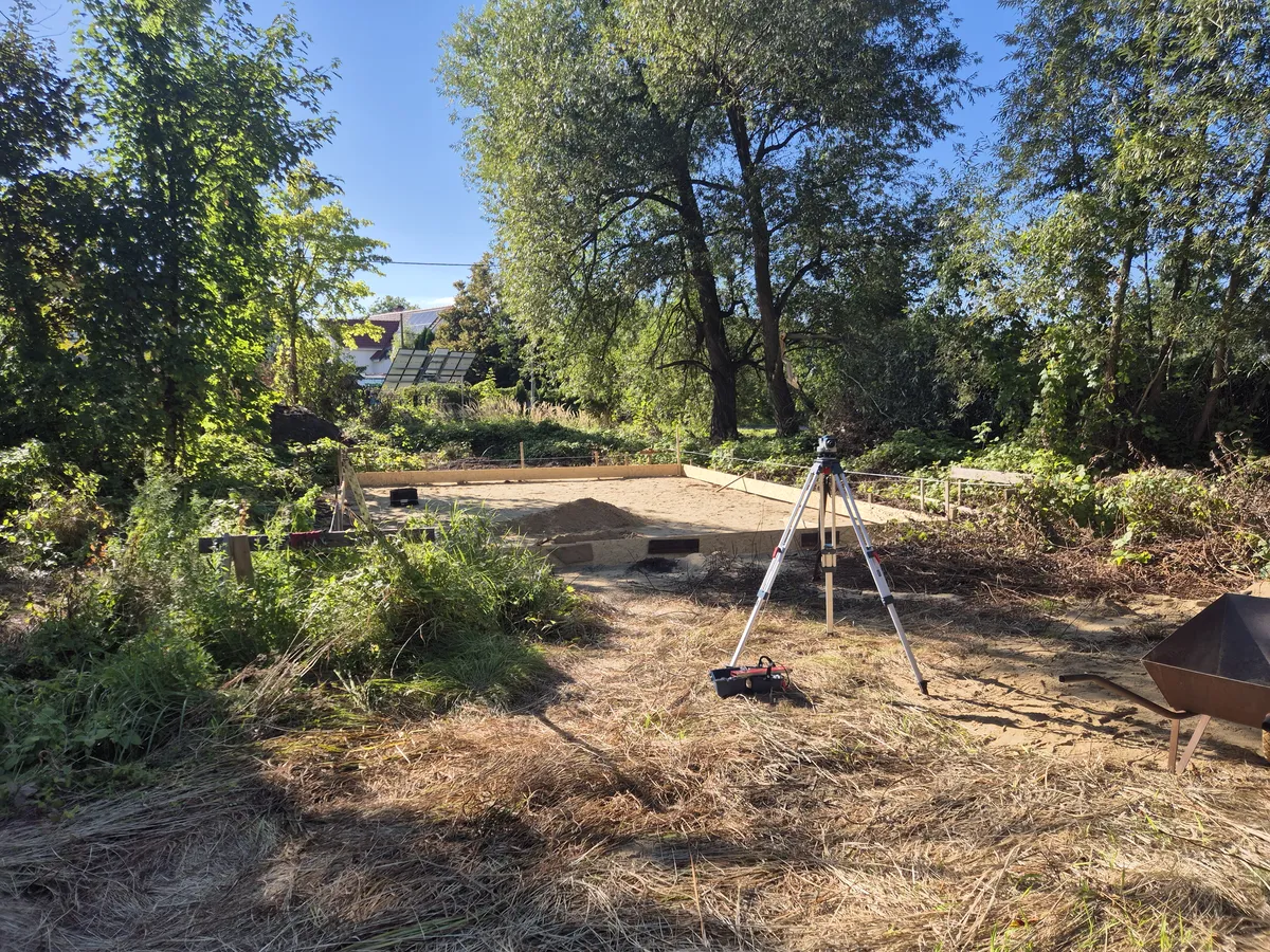
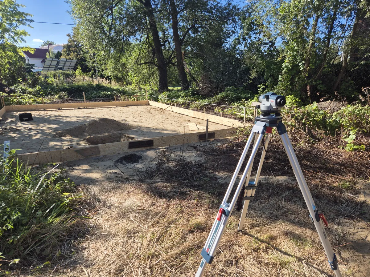
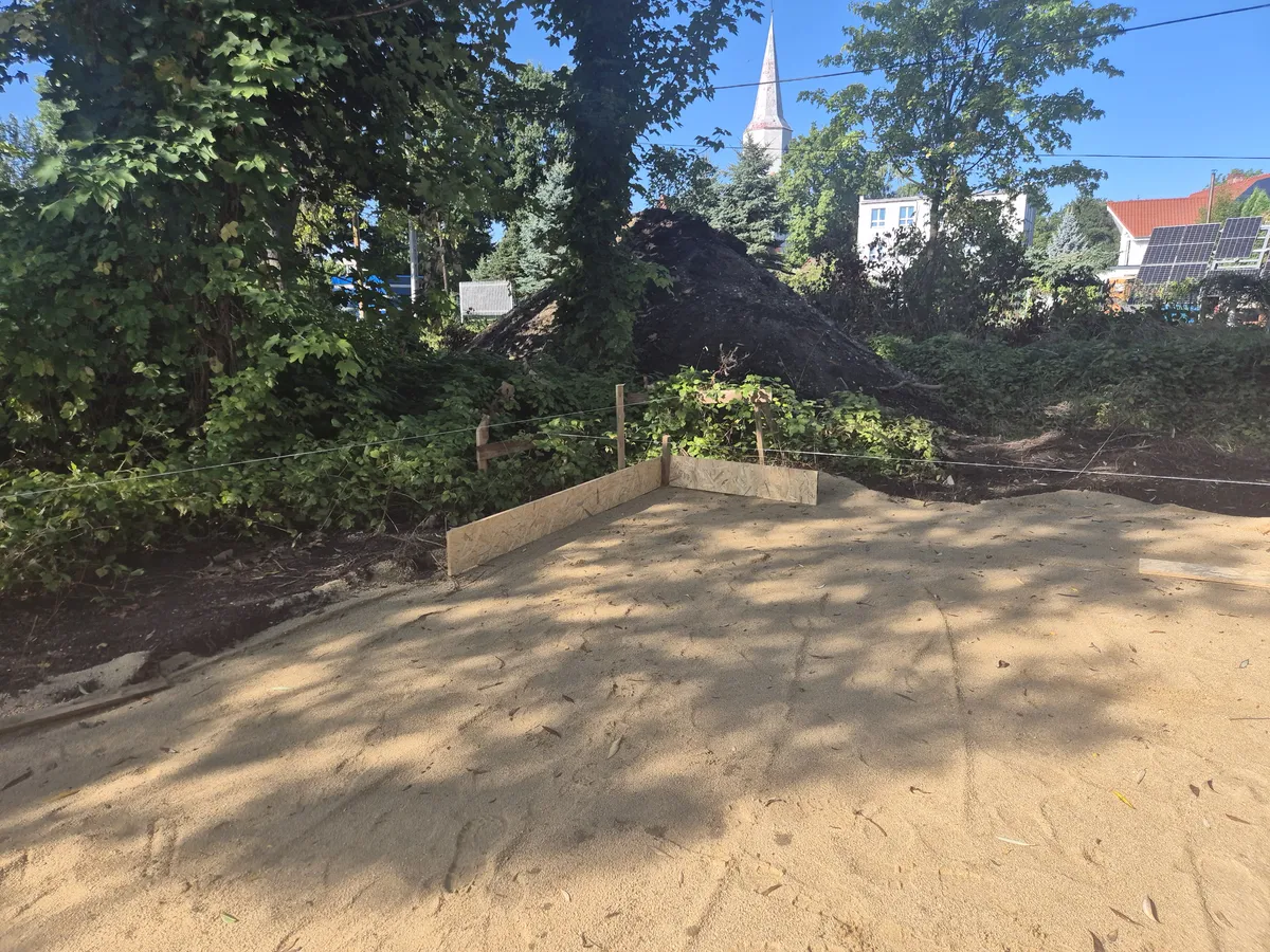
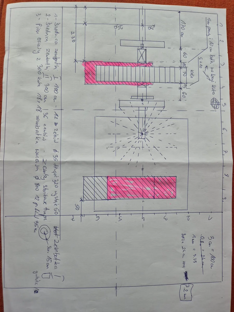
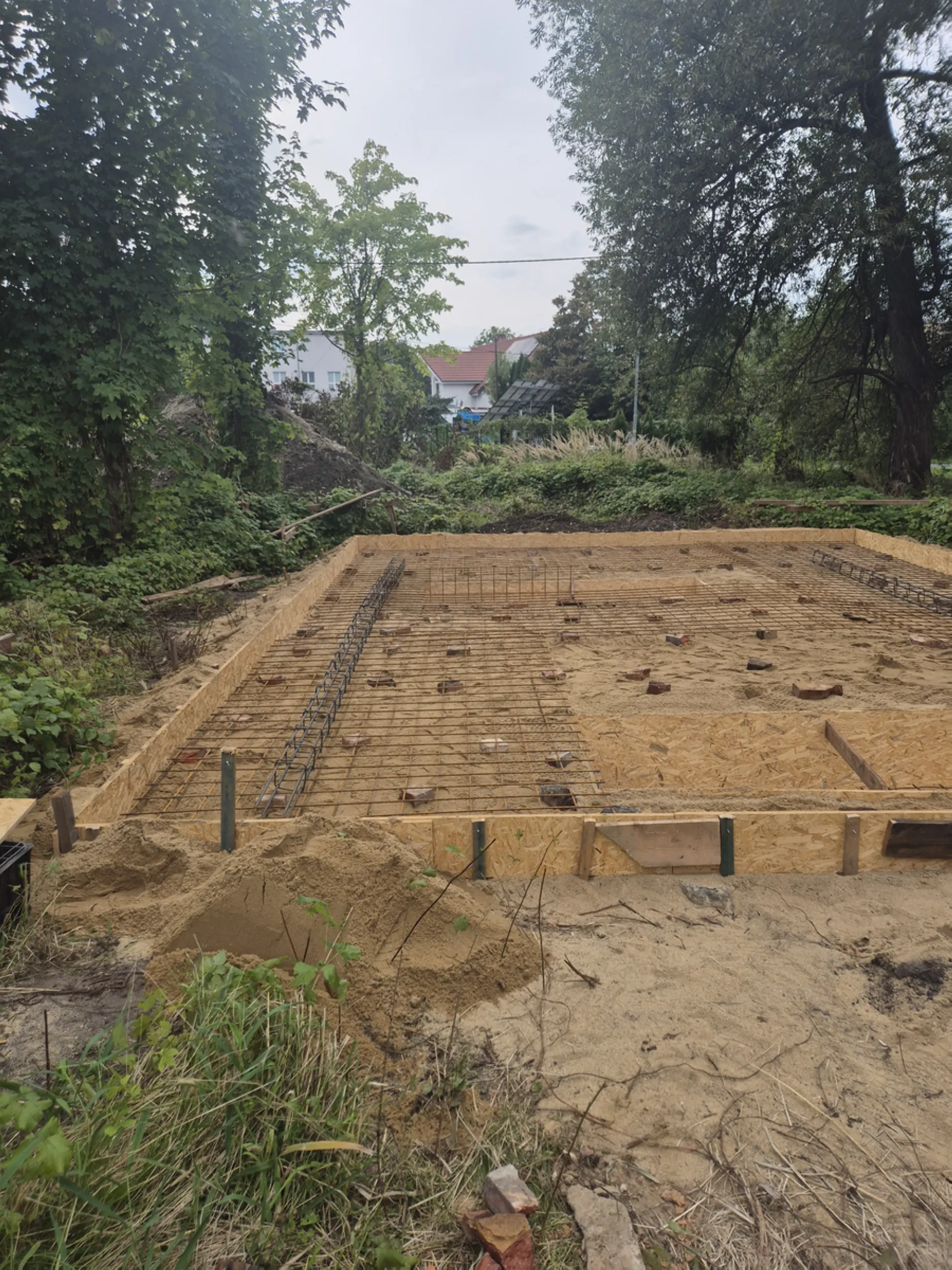
1 – Site preparation and setting out the Rurmus foundation
The work involved preparing the site for the construction of the “Rurmus” by marking the facility’s location, establishing structural axes, and conducting the geodetic measurements necessary for the device’s precise positioning. Activities included marking the boundaries of the future foundation slab, checking levels, and preparing the subgrade for subsequent construction work.
The scope of work also encompassed site grading using heavy machinery, leveling the ground, and preparing the surface for formwork installation. Key structural points were marked out, serving as reference points for all subsequent assembly and construction tasks.
Measurement accuracy, proper subgrade preparation, and adherence to specified dimensions were crucial for the subsequent installation of the foundation, the water wheel, and the wooden structure of the “Rurmus.”
- rurmus project -
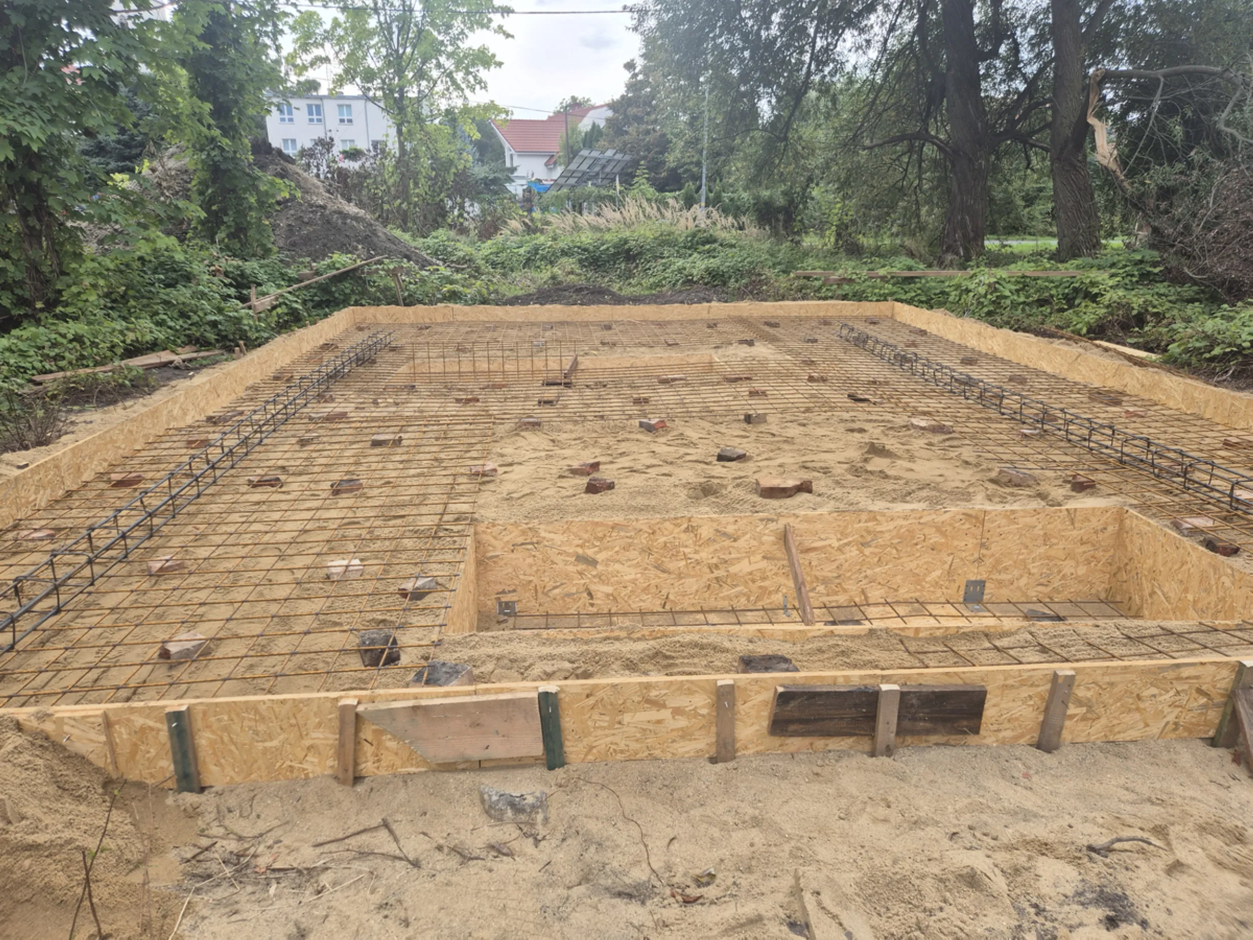
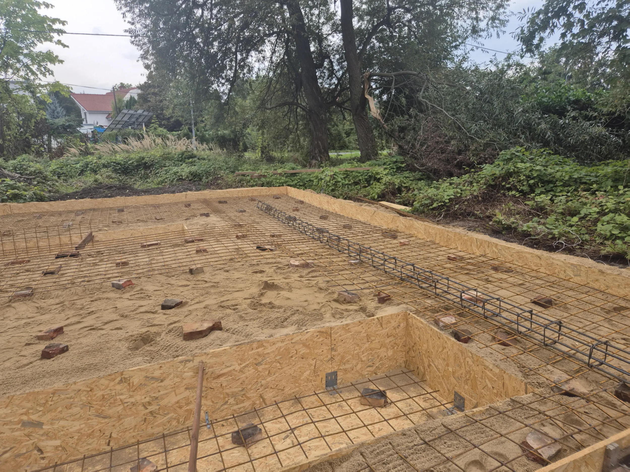
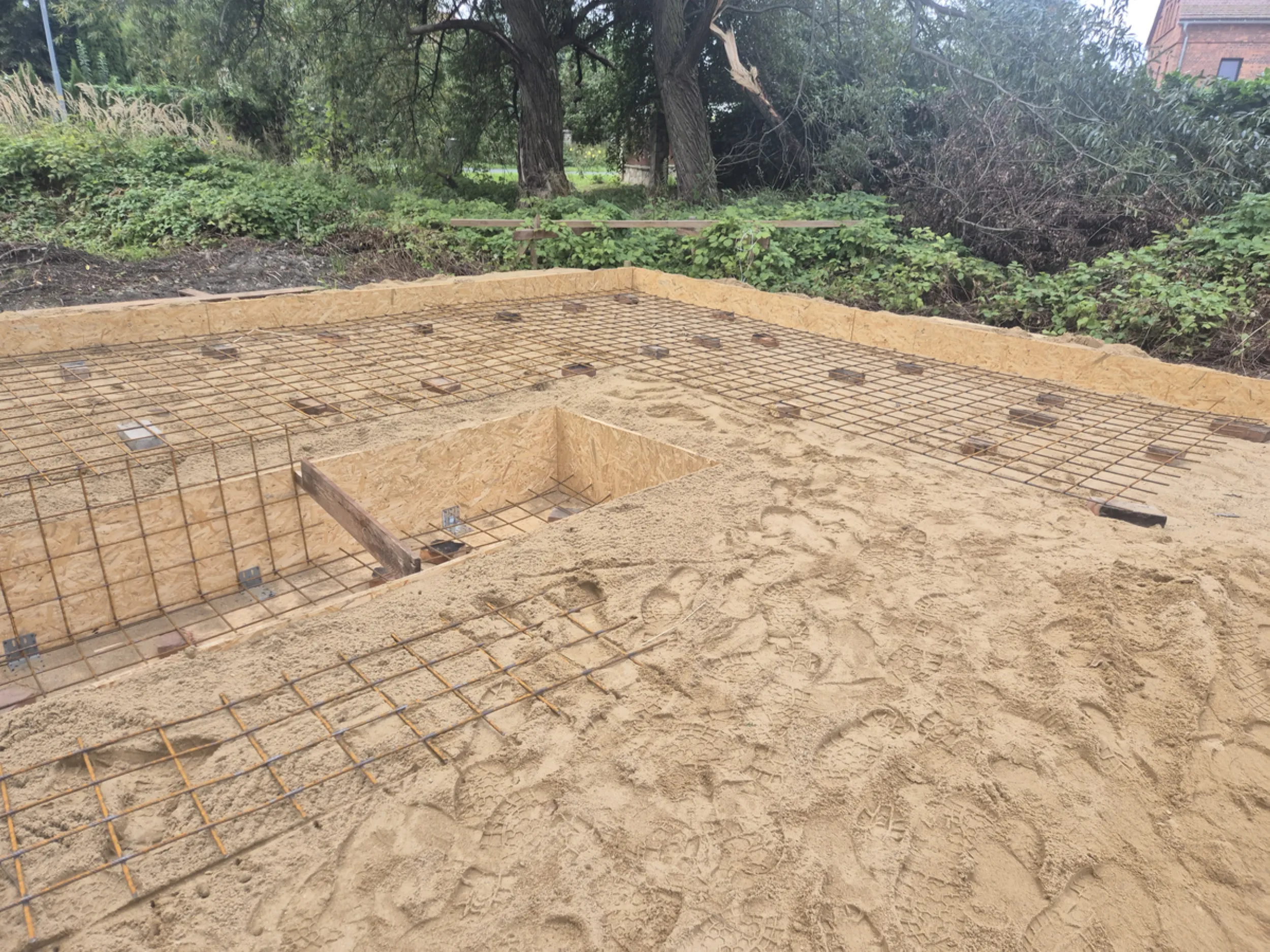
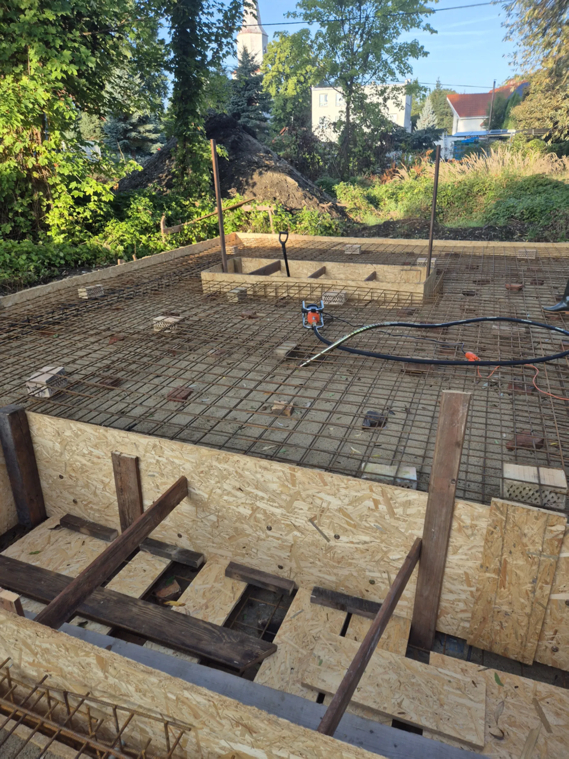
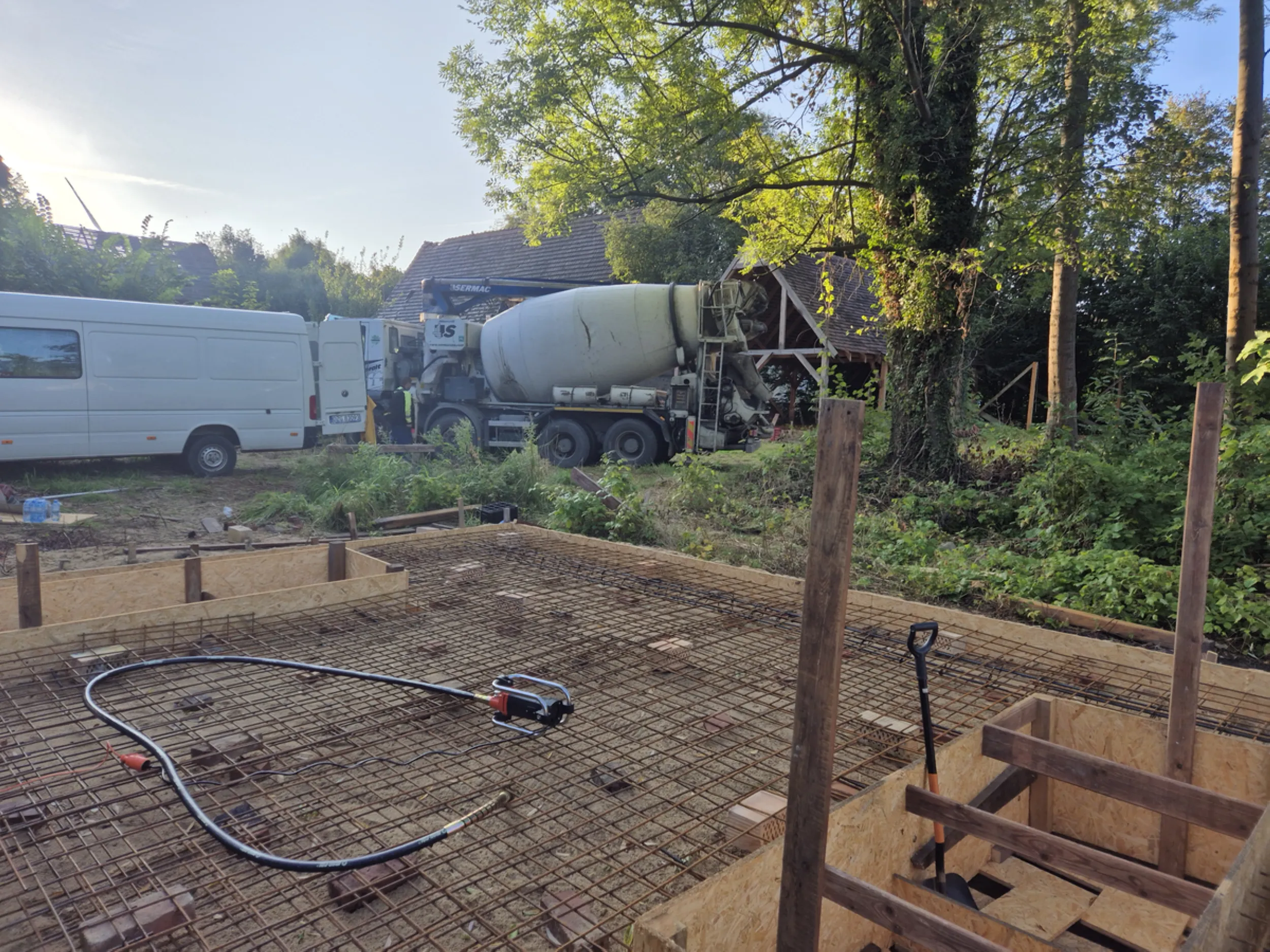
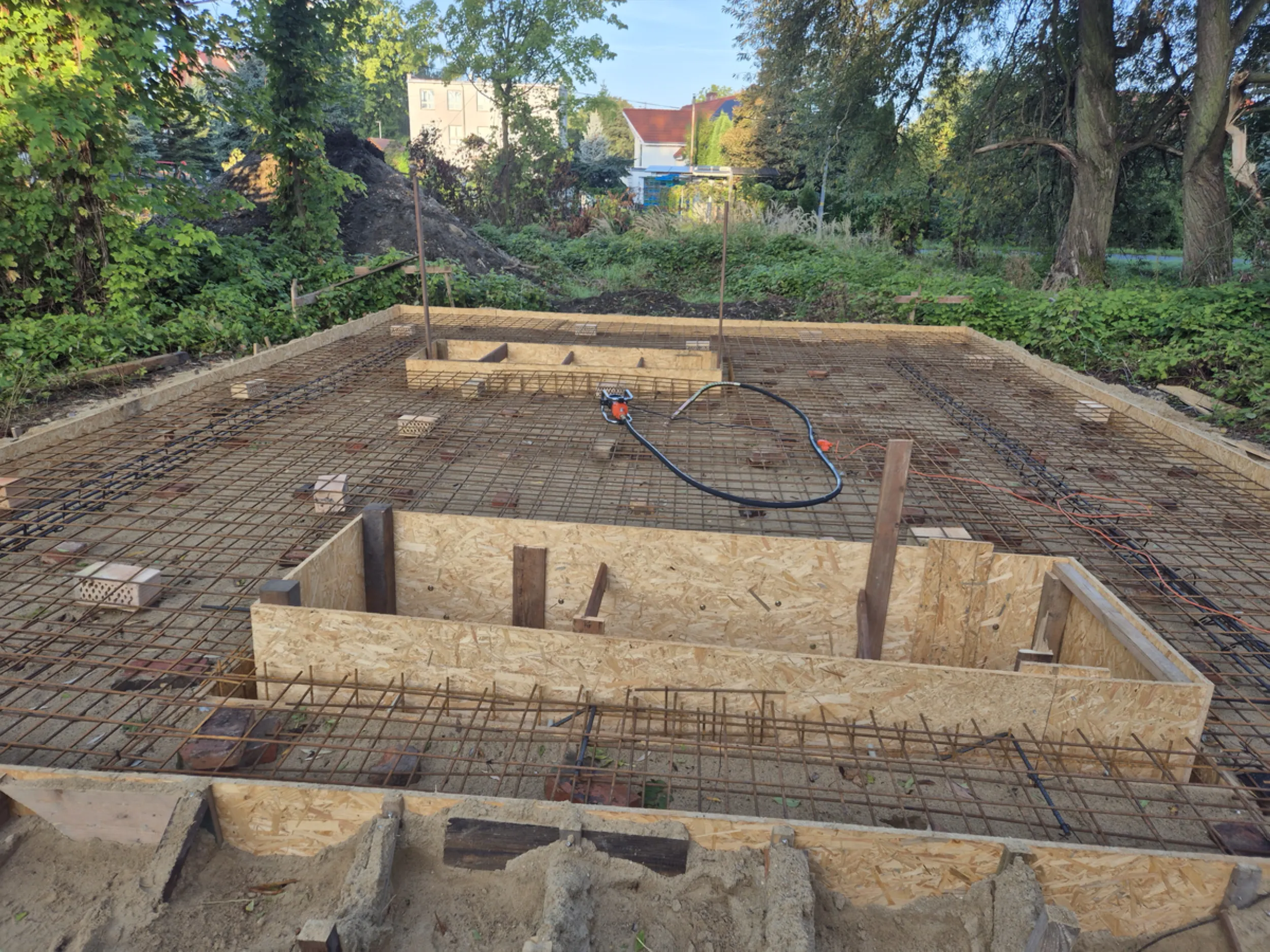
2 – Reinforcement of the Rurmus foundation slab
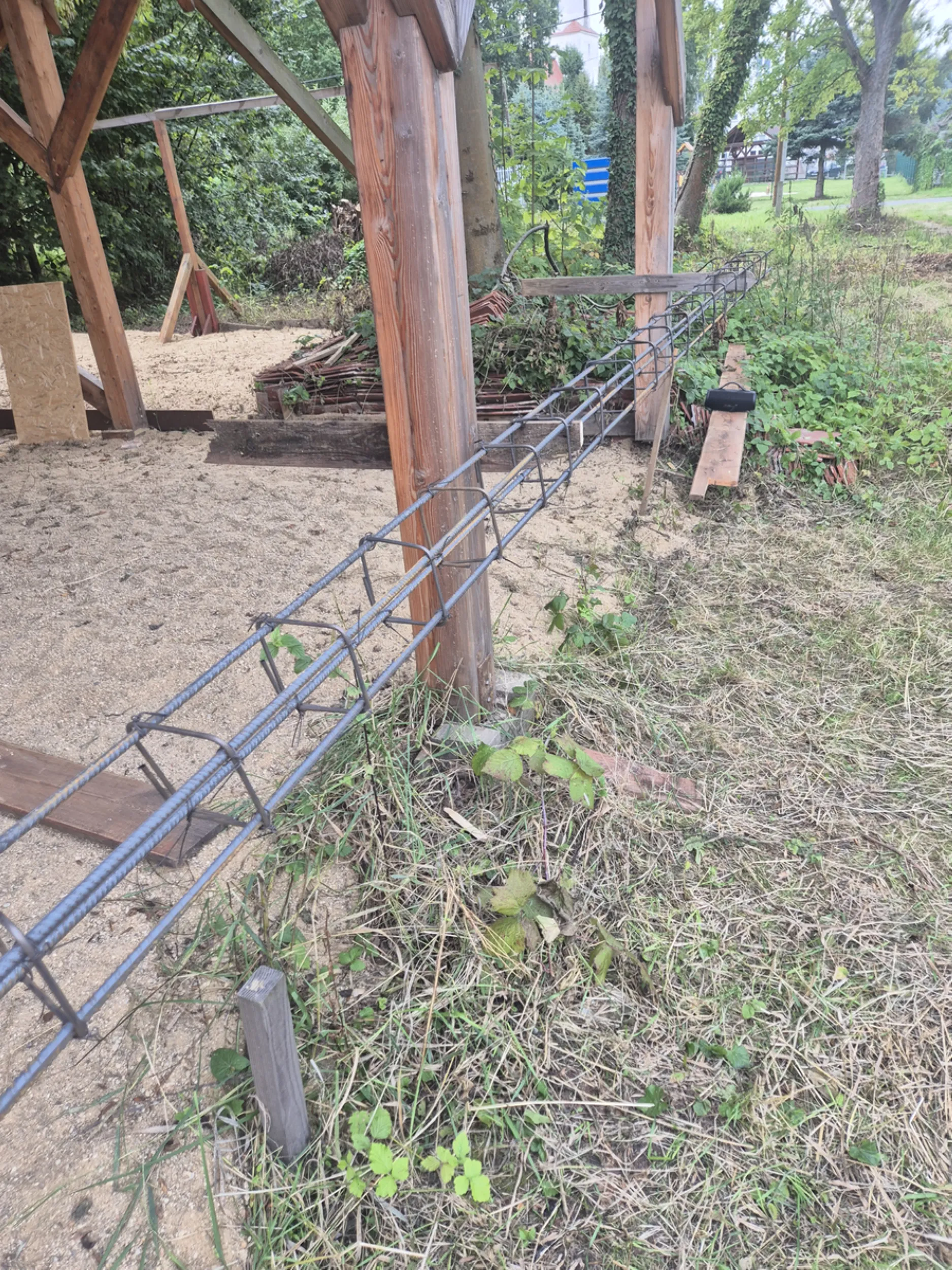
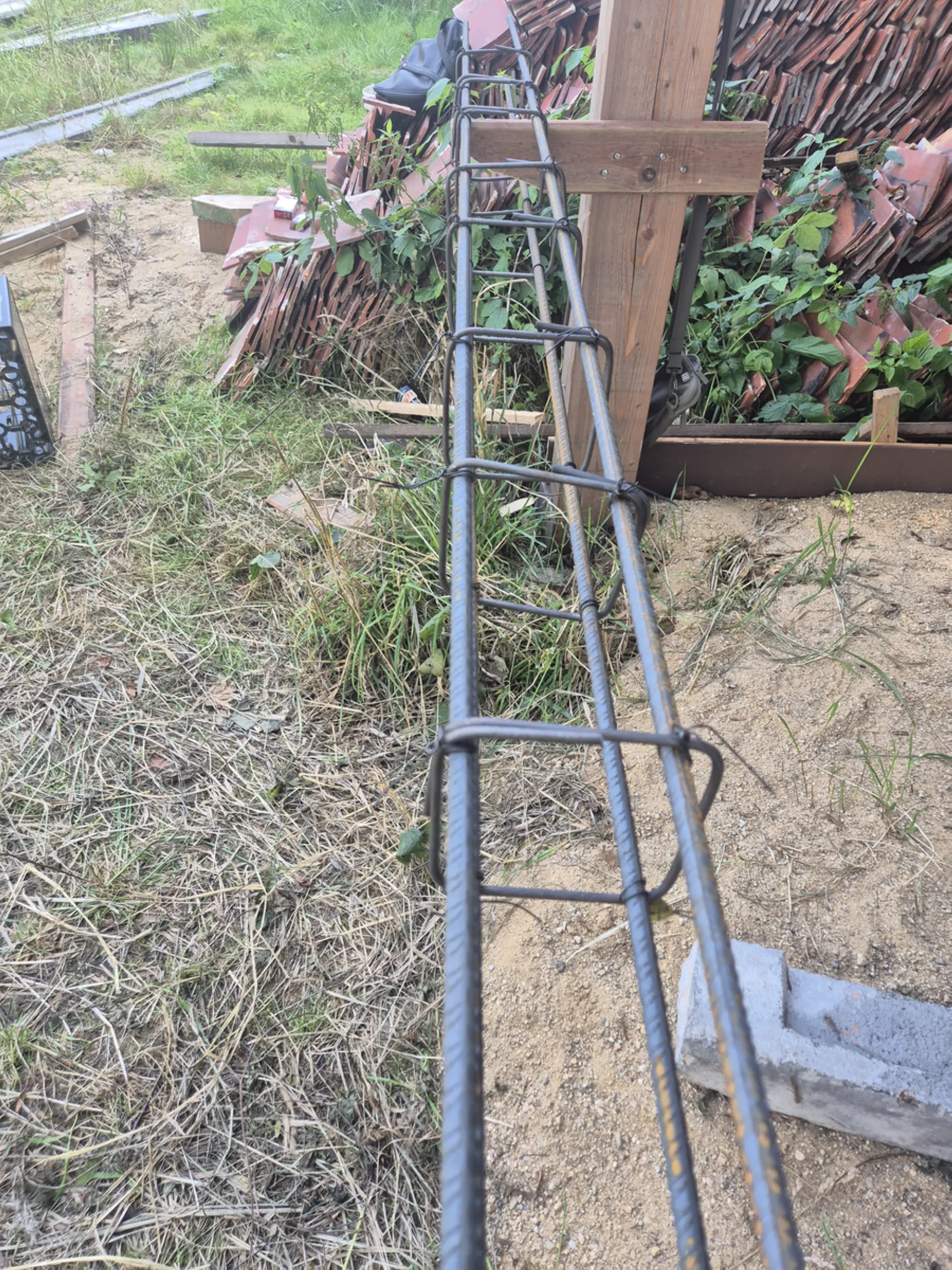
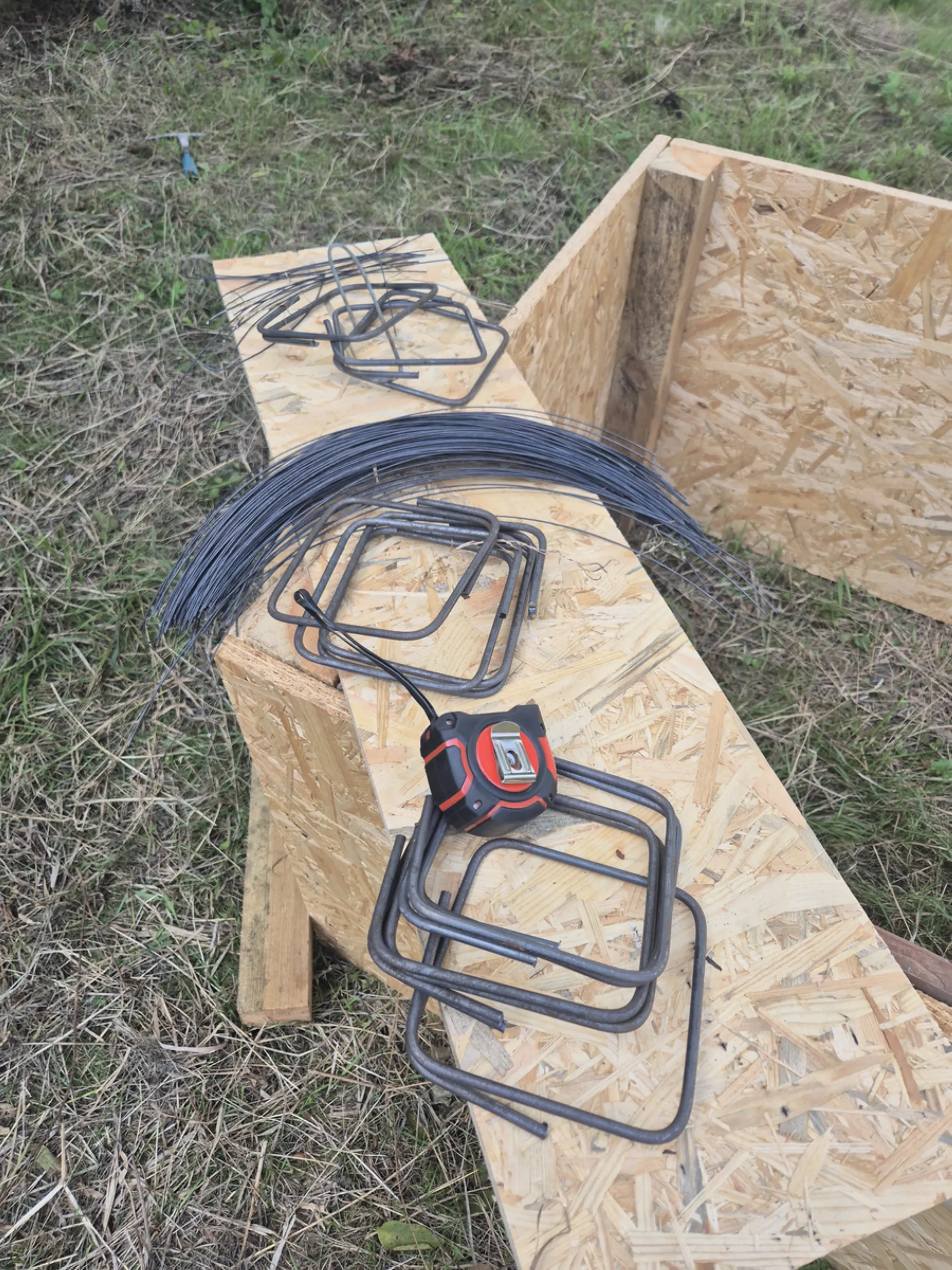
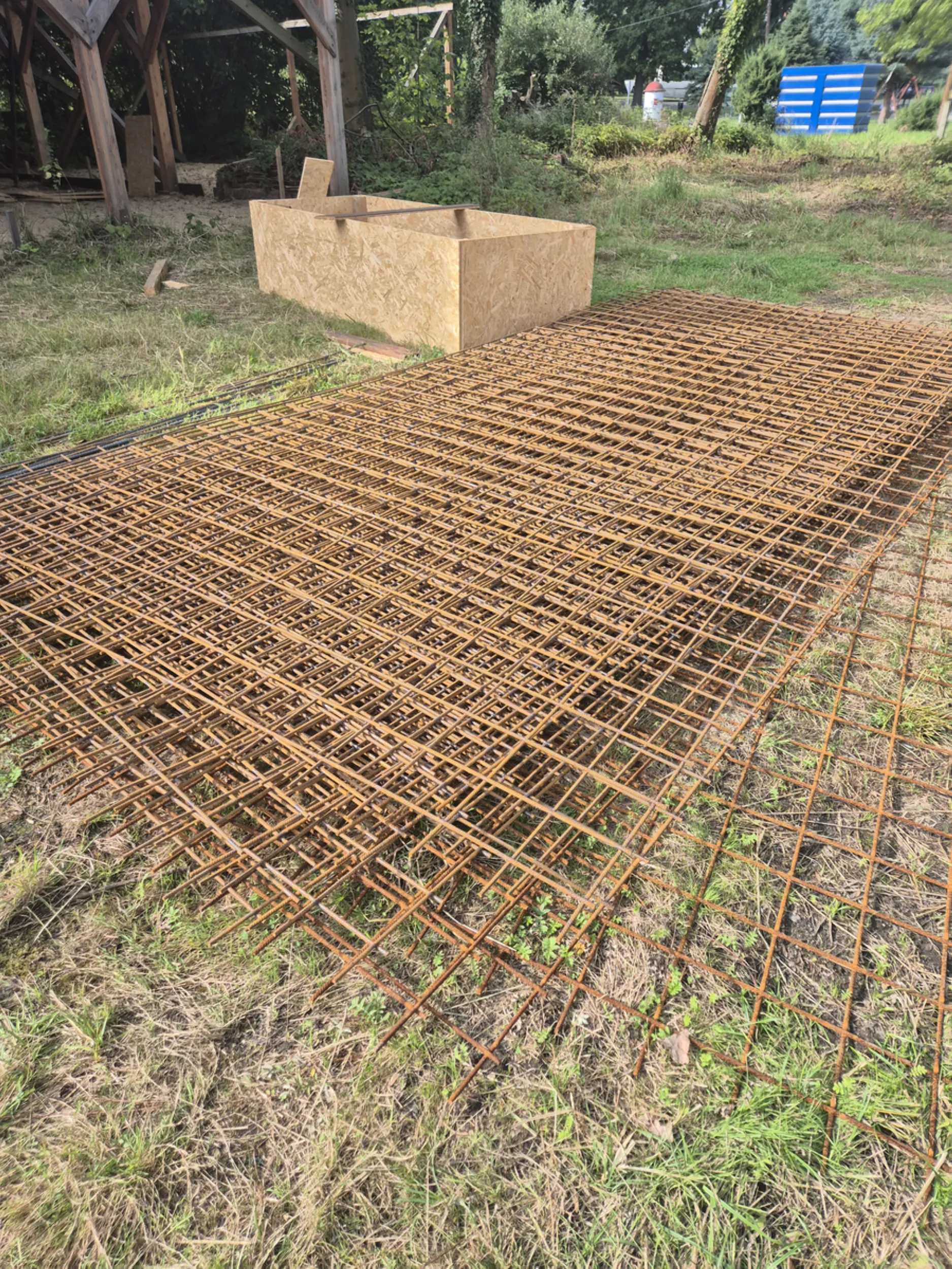
Reinforcement preparation involved positioning steel mesh, reinforcing bars, and spacers designed to ensure the correct concrete cover. Additional reinforcement was installed within the foundation at points designated to bear the heaviest loads from the tower structure, the water wheel, and the drive mechanisms.
The work shown includes tying the reinforcement, checking bar spacing, and preparing the central section of the foundation to accommodate the device’s technical components. Every part of the steel framework was aligned with the technical documentation to ensure the future structure’s required rigidity and durability.
Although the reinforcement would be hidden from view once construction was complete, it is the element responsible for load-bearing and the long-term stability of the entire structure.
- rurmus project -
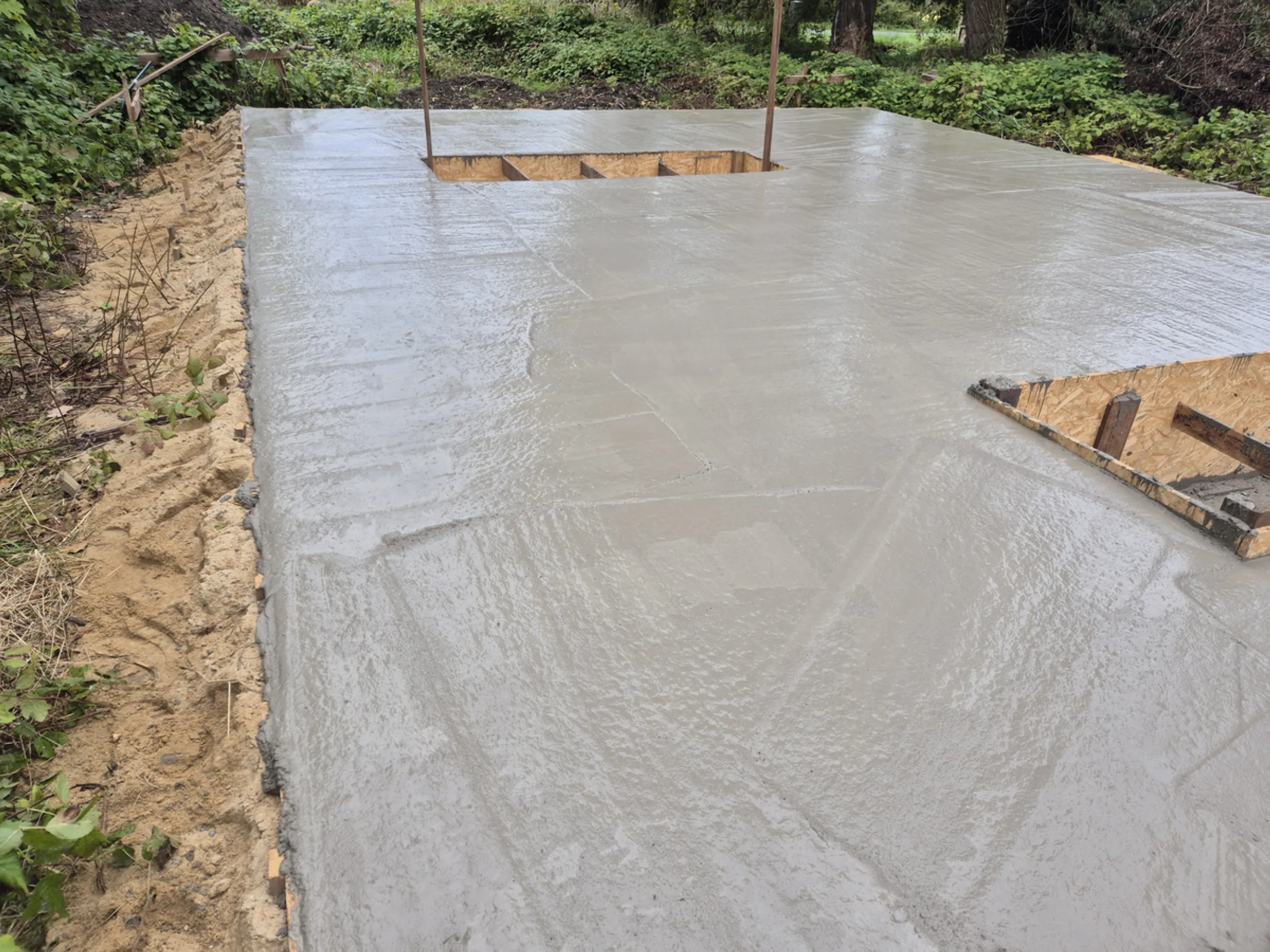
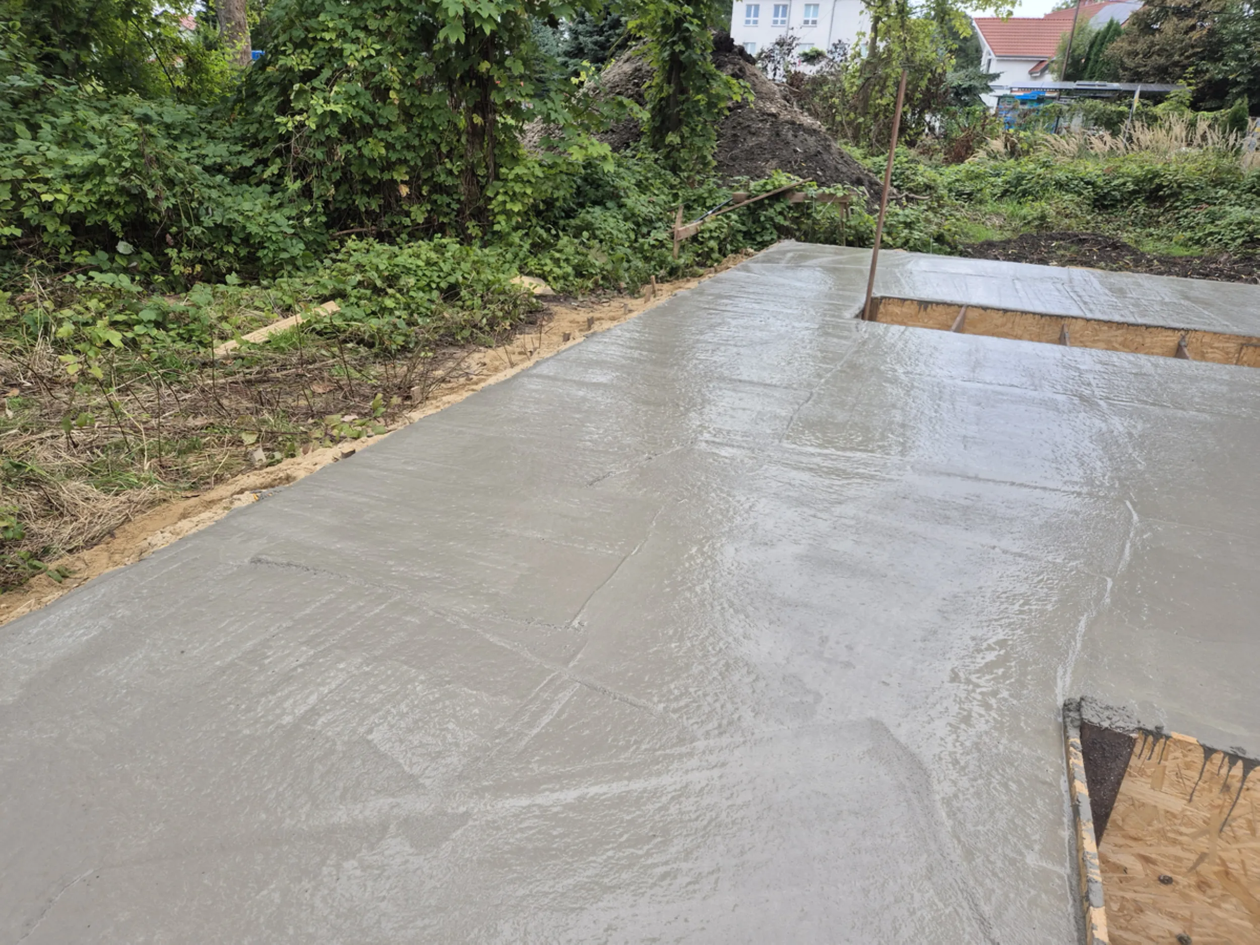
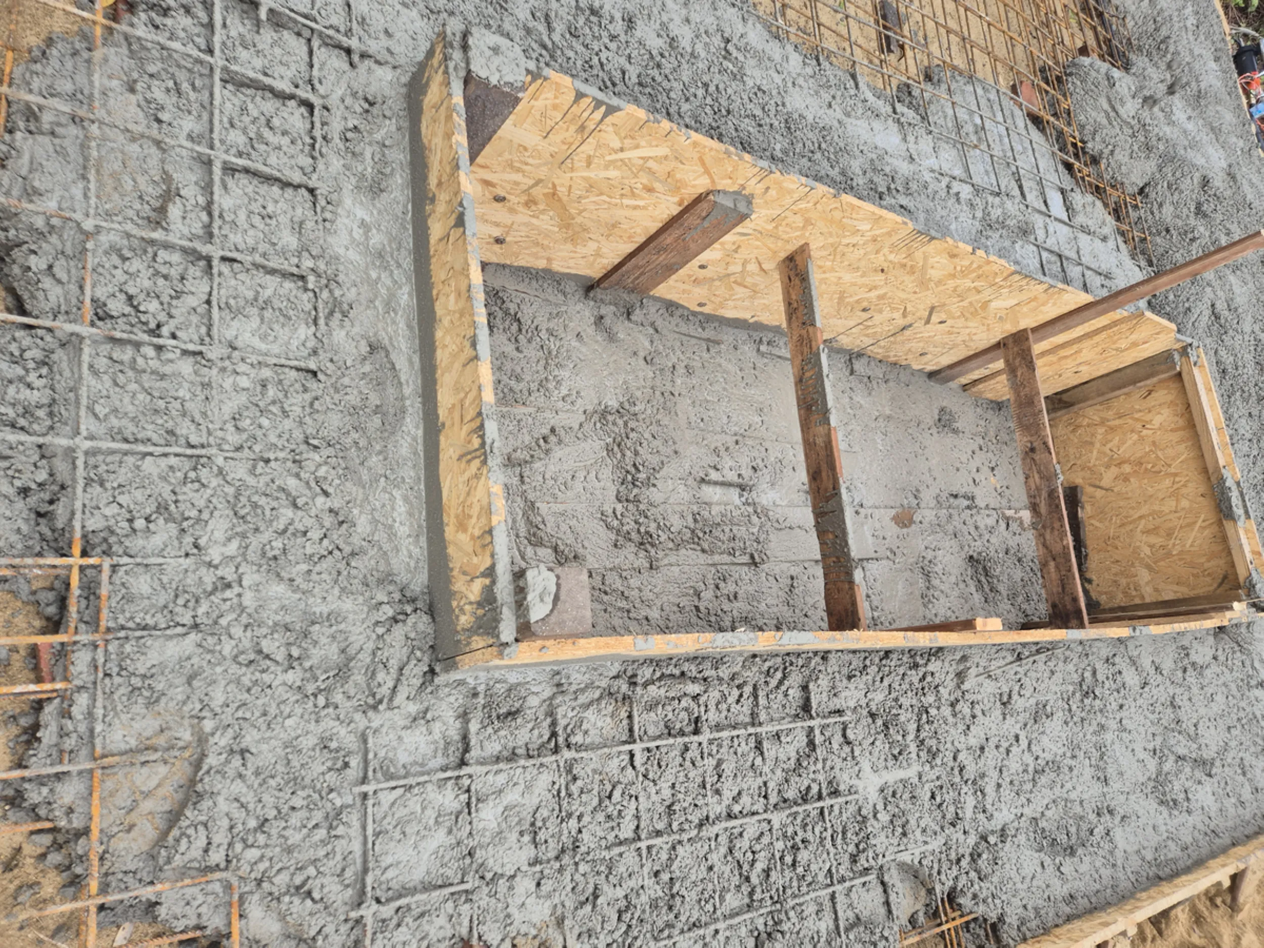
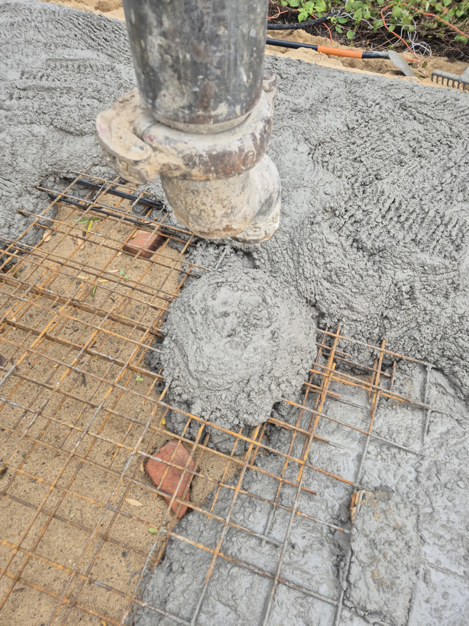
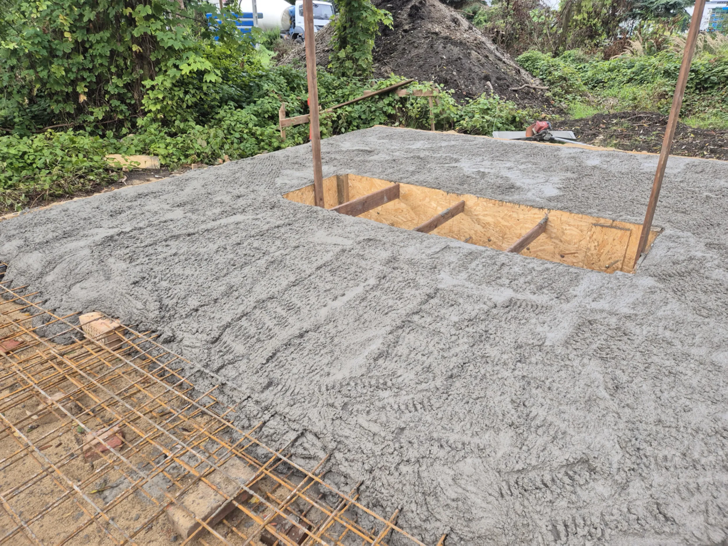
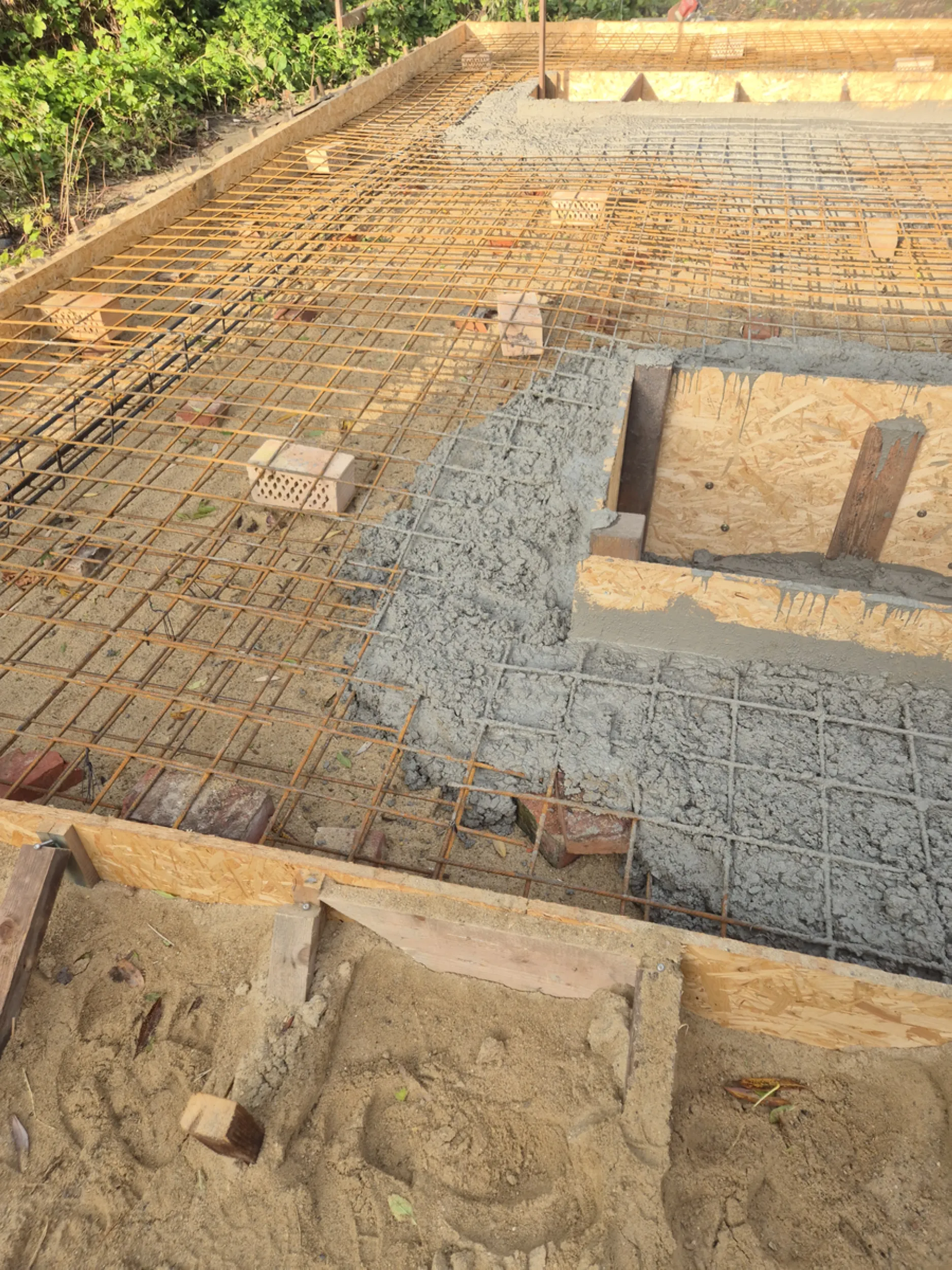
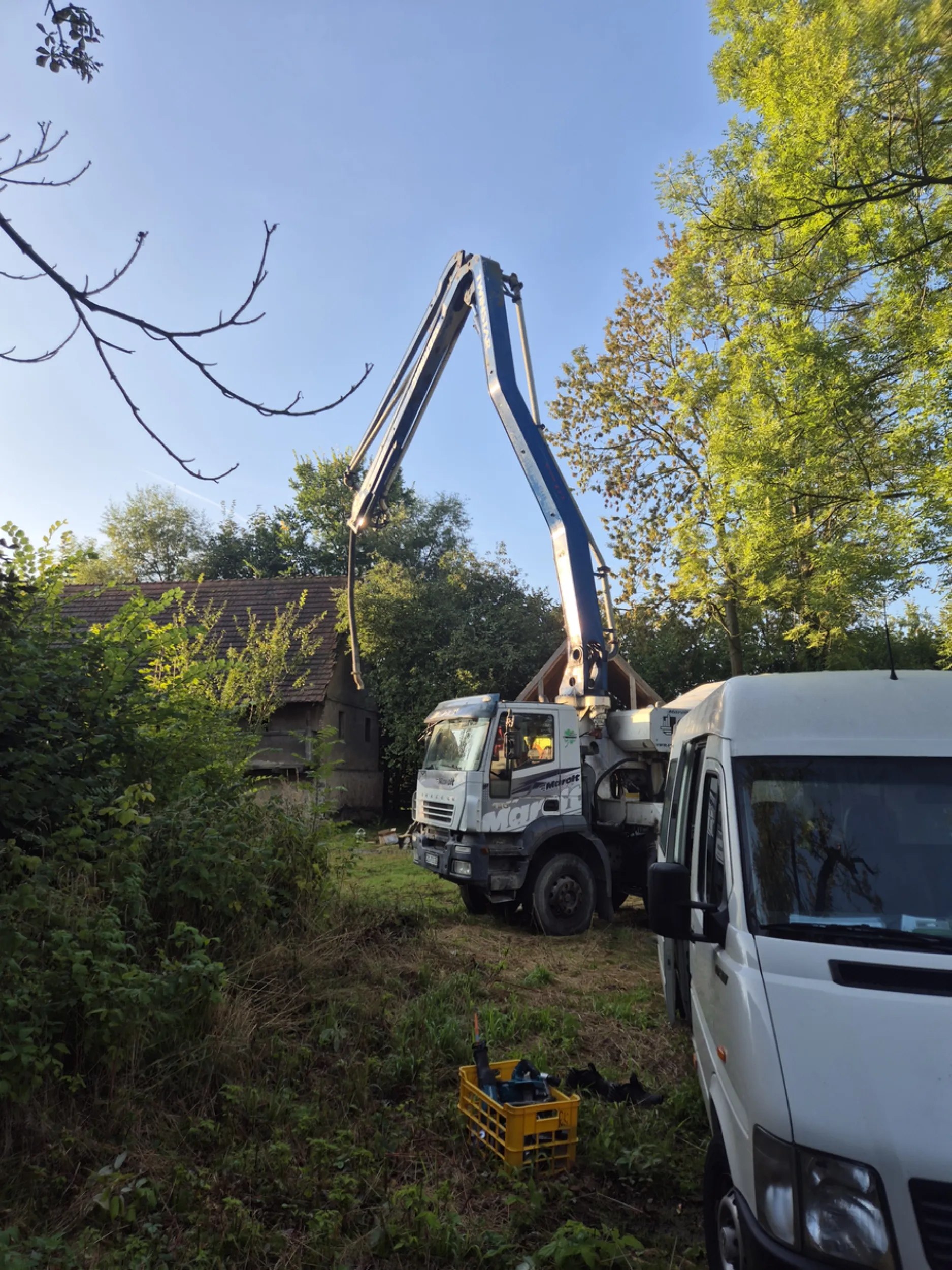
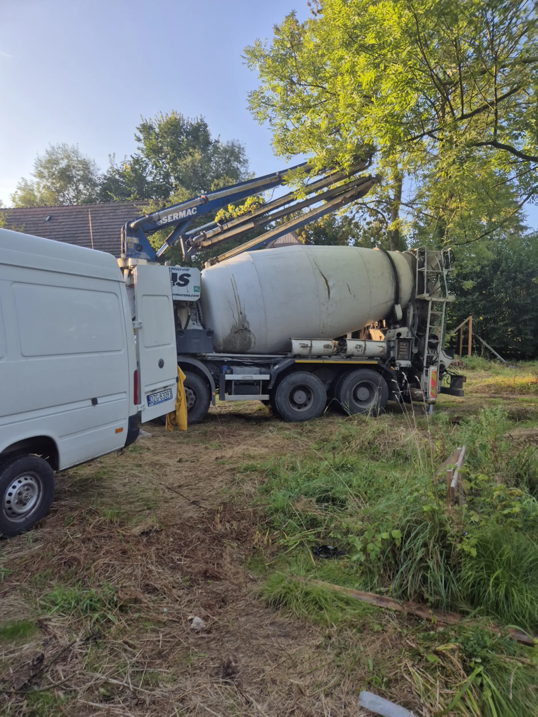
3 – Concreting the Rurmus foundation slab
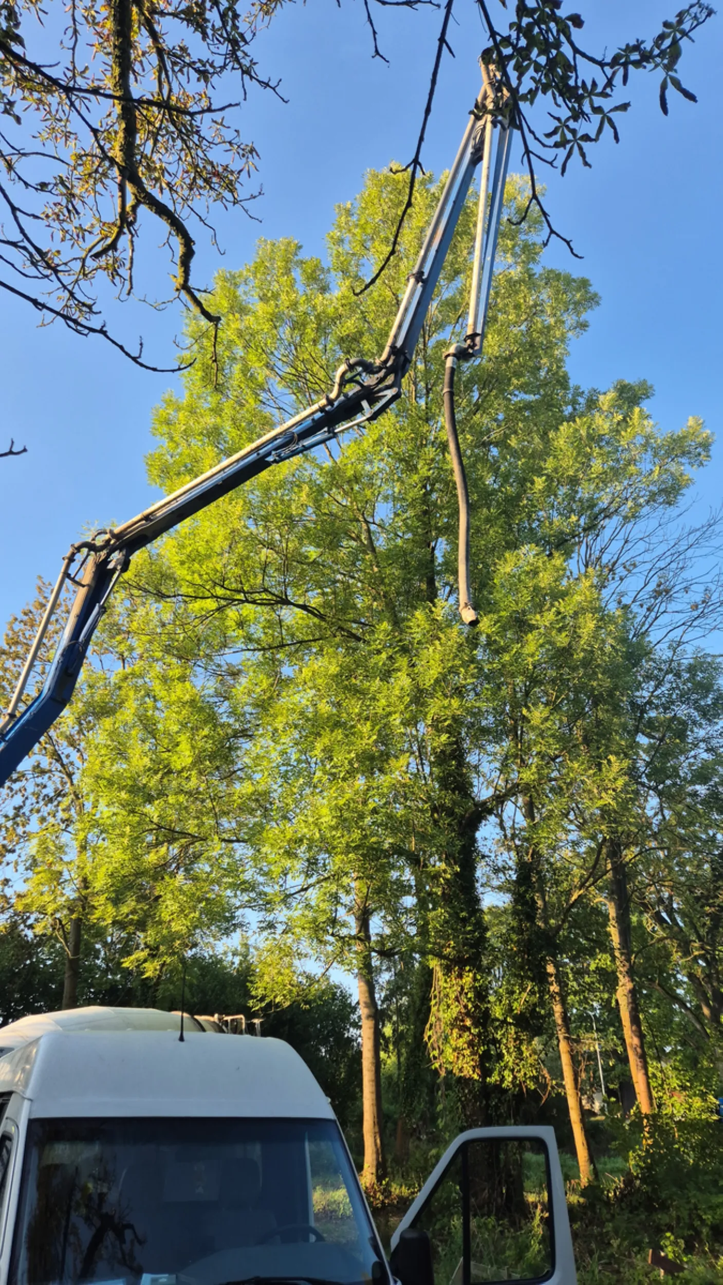
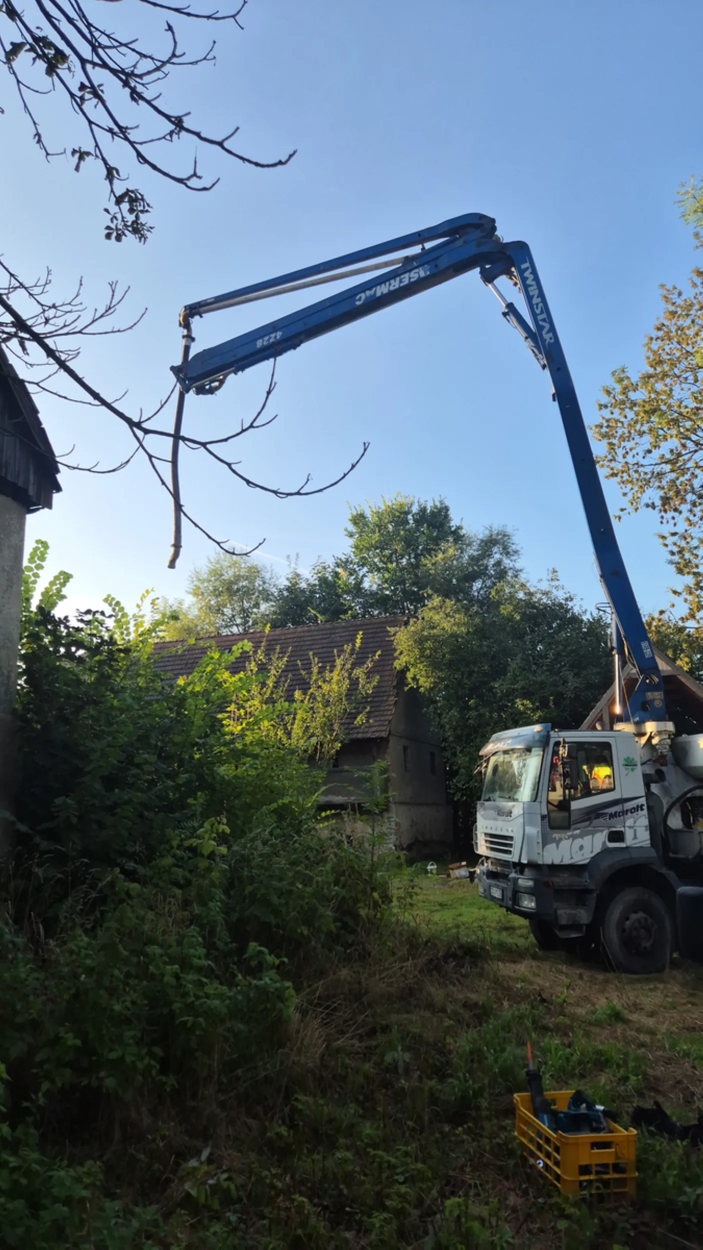
The work involved constructing a monolithic foundation slab that serves as the base for the entire Rurmus structure. Concrete mix was poured into the previously prepared formwork and reinforcement, then evenly distributed and compacted. Areas with a high density of reinforcement and zones designated for the subsequent installation of structural components required particular attention.
The images show the concrete placement, level monitoring, slab thickness checks, and surface leveling. Adhering to the correct execution parameters was crucial for the structure’s future stability and the proper transfer of loads generated by the tower, water wheel, and drive mechanisms.
The foundation slab is the heaviest and most heavily loaded element of the entire structure. Its durability, safety, and the maintenance of the correct geometry for all Rurmus components depend on the quality of its construction.
- rurmus project -
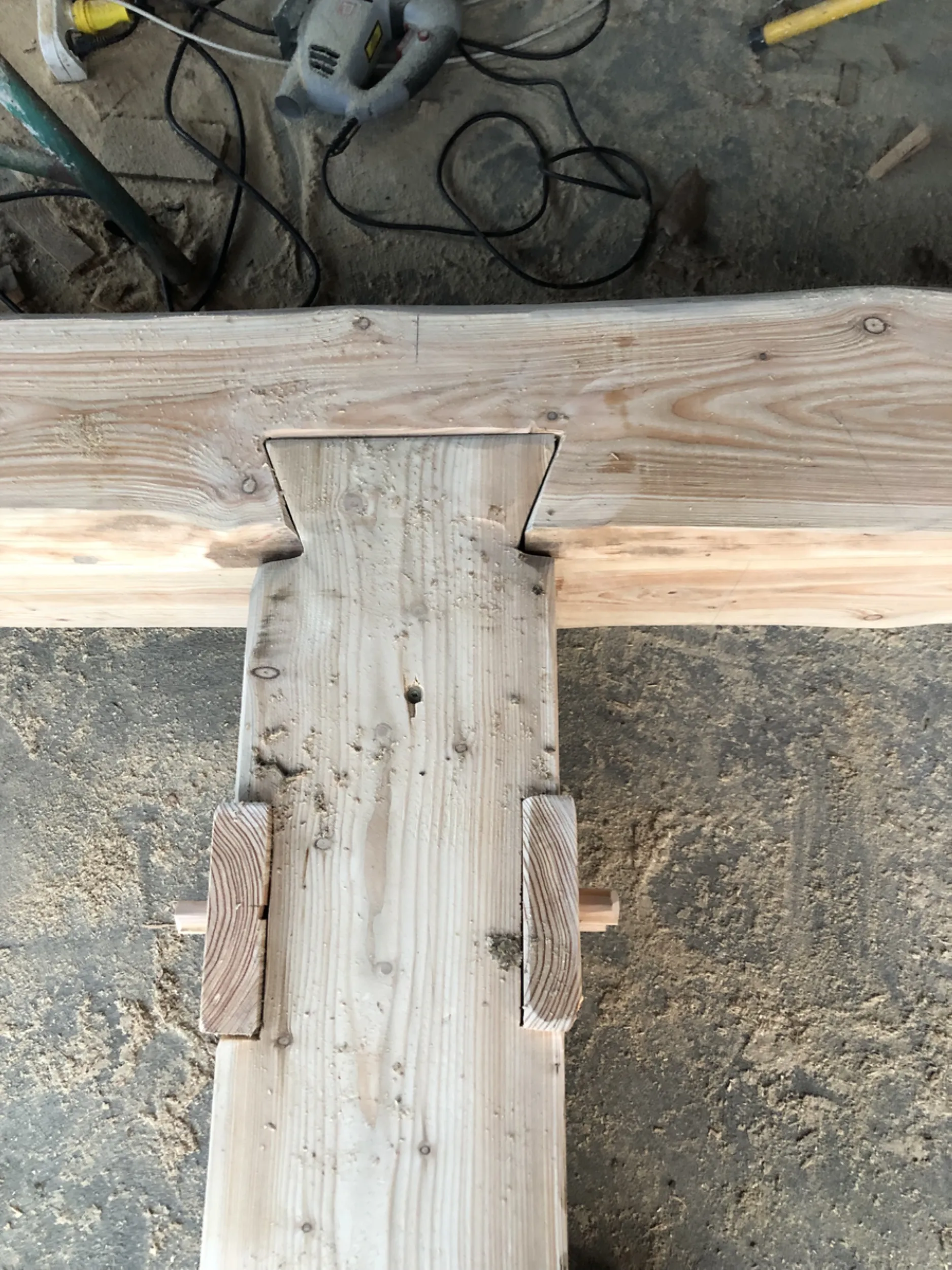
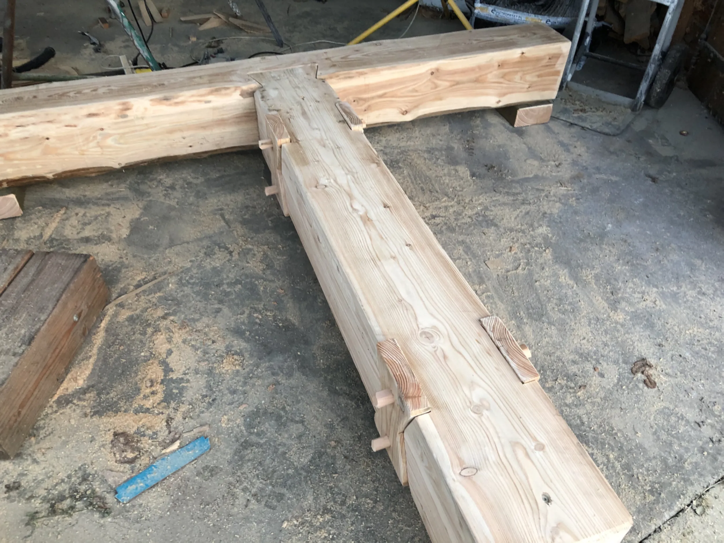
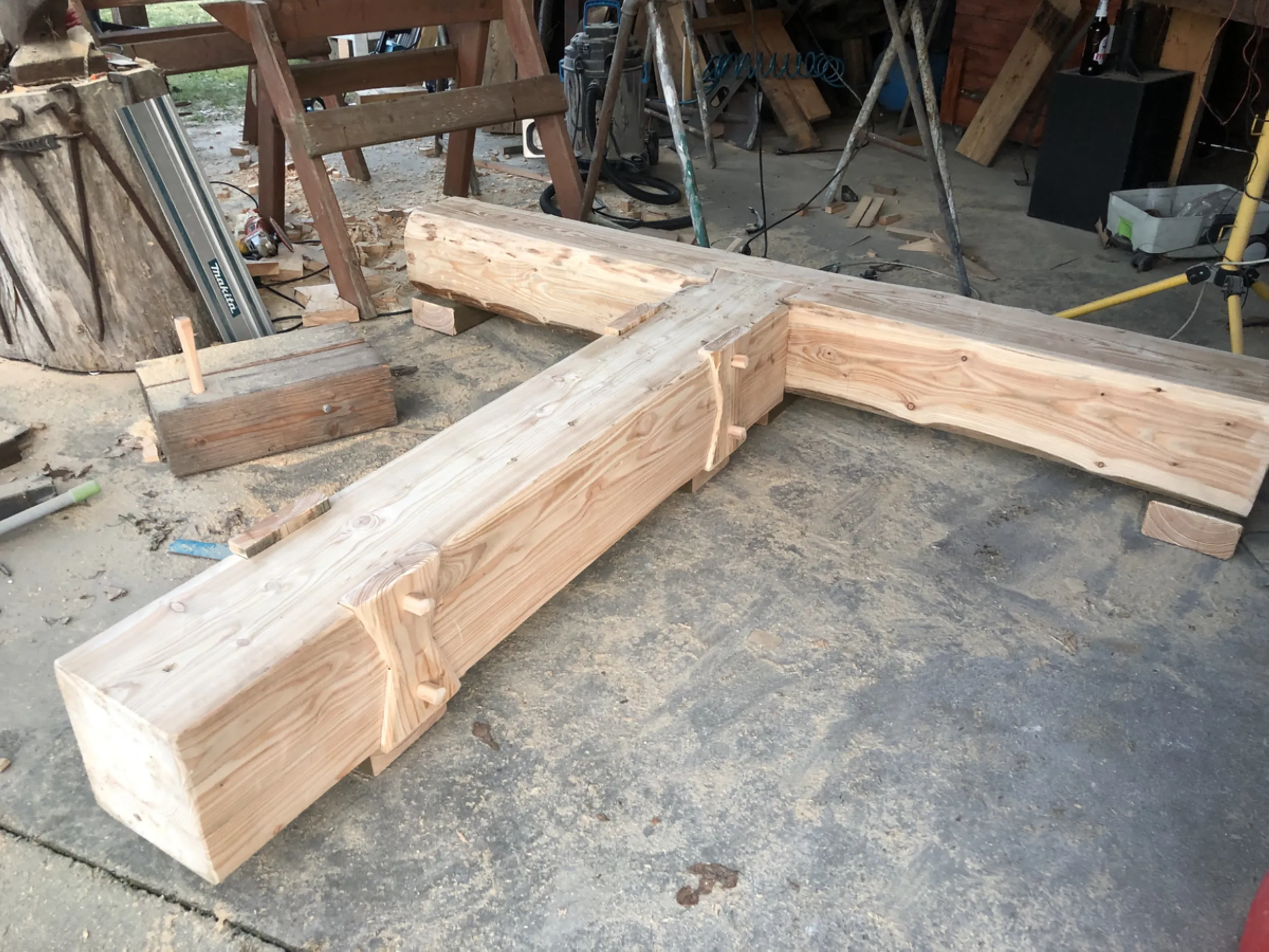
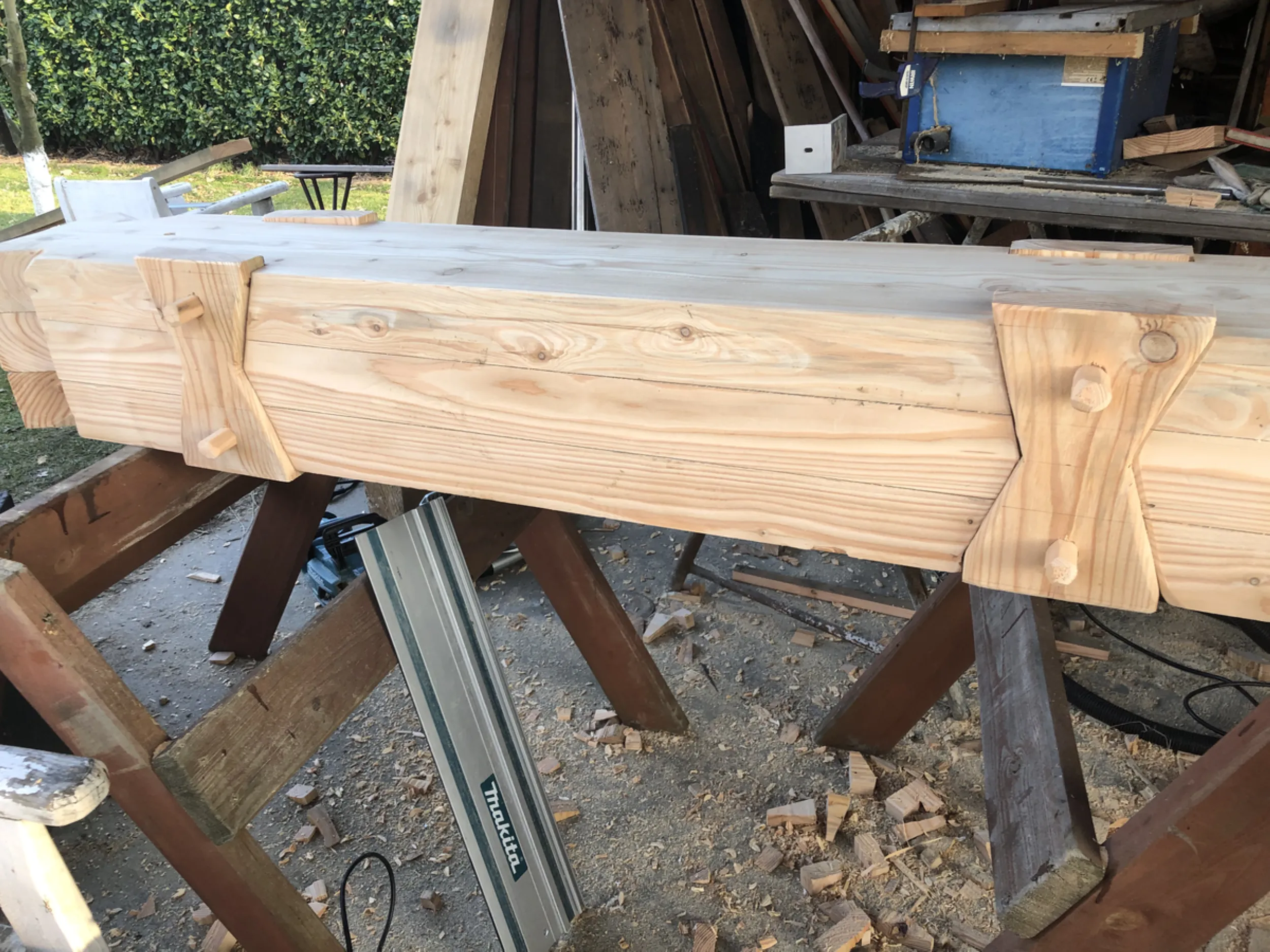
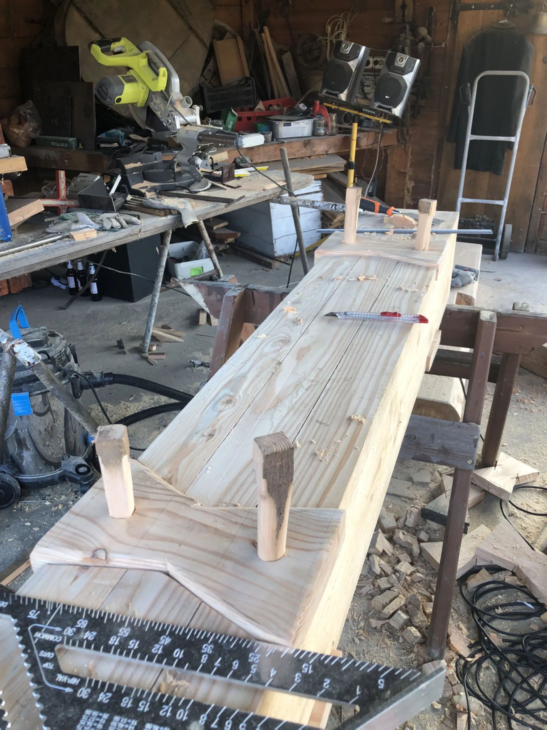
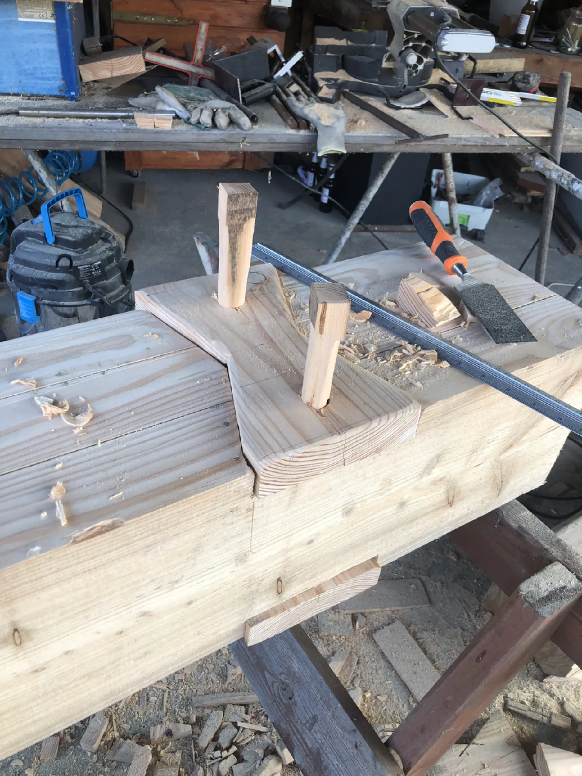
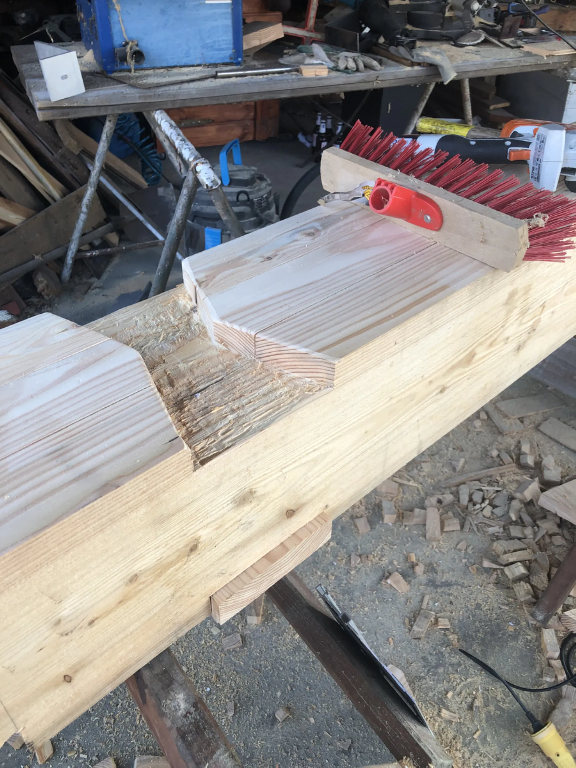
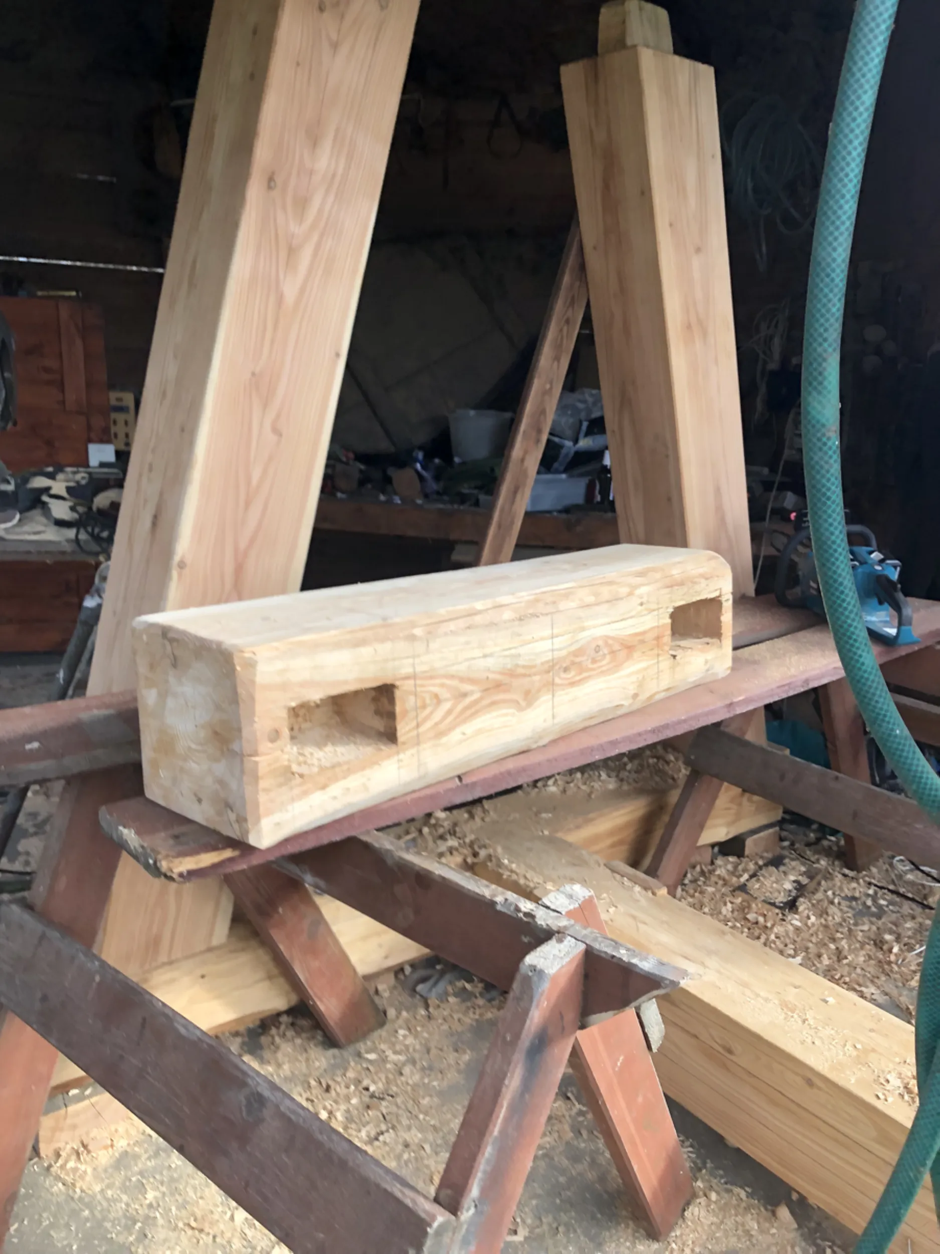
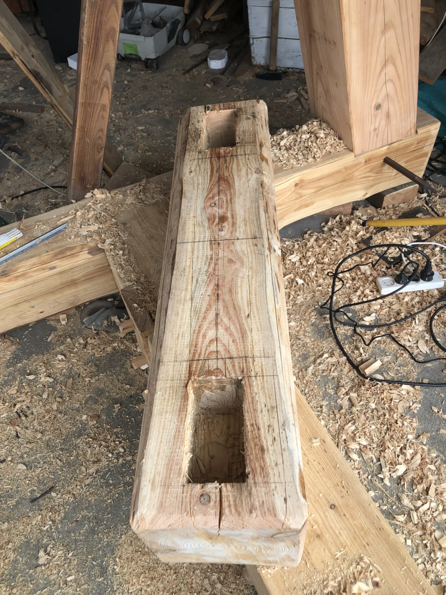
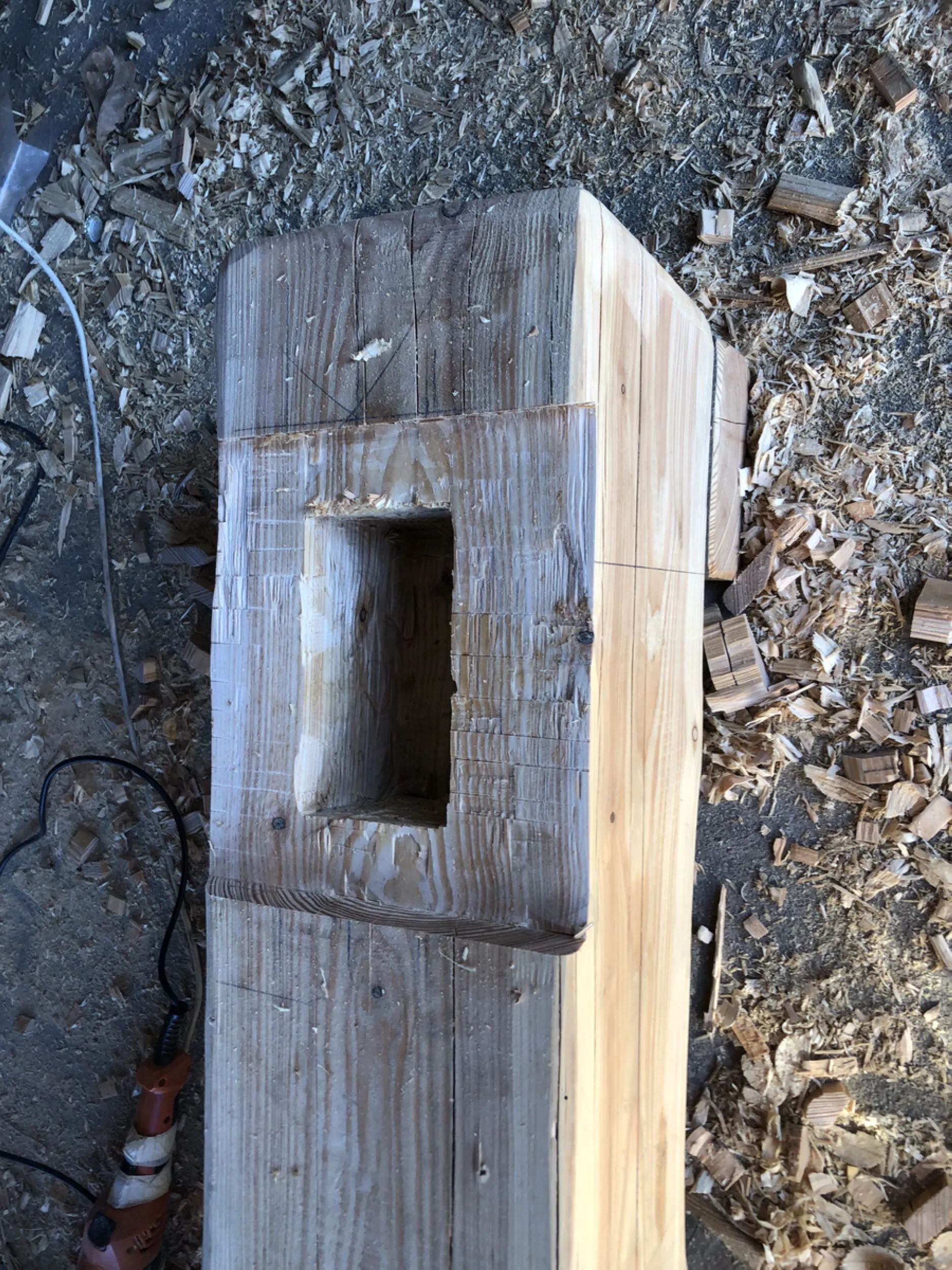
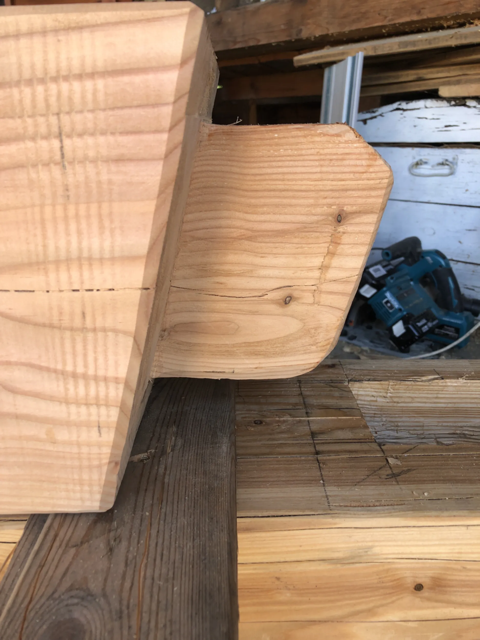
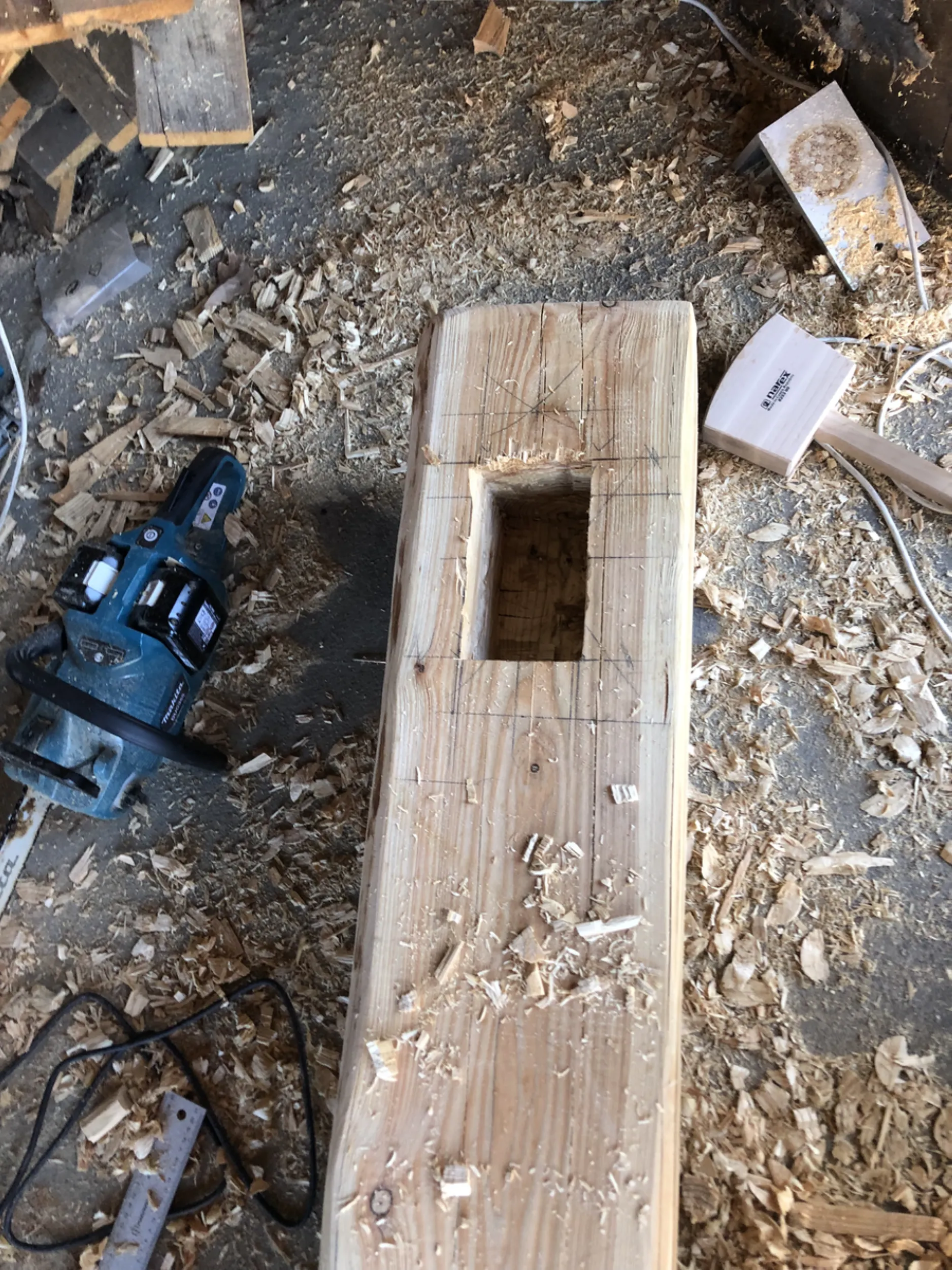
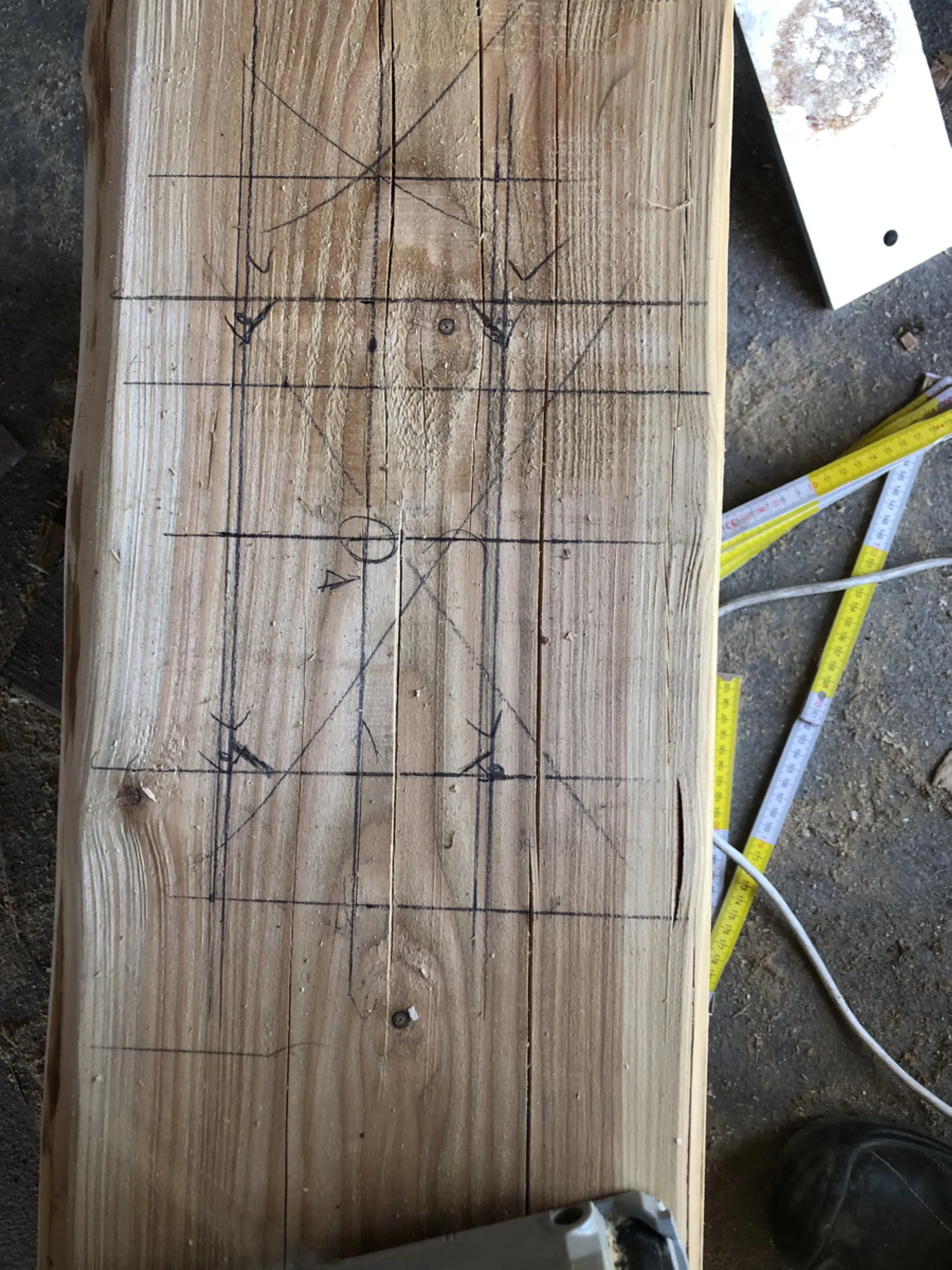
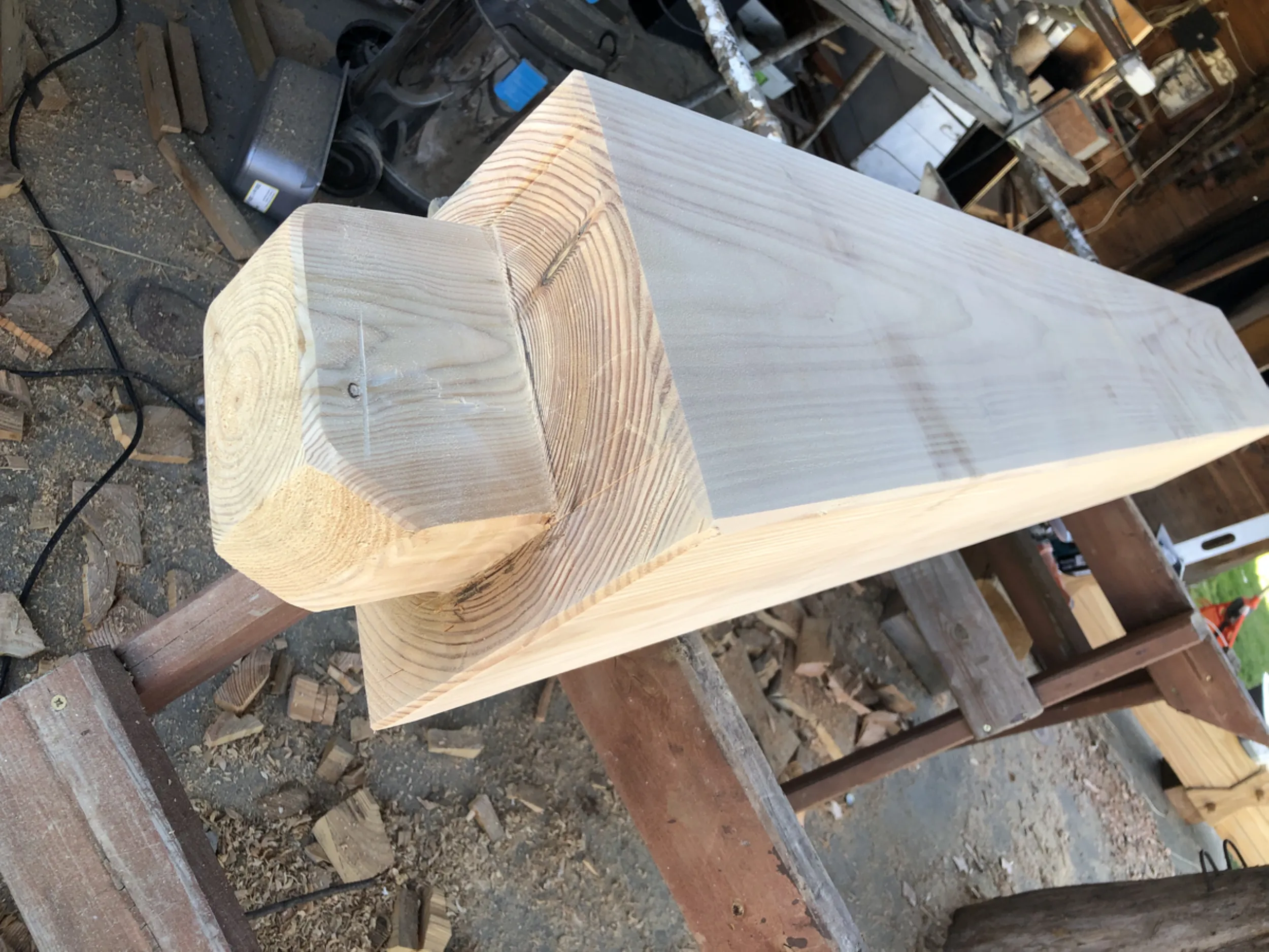
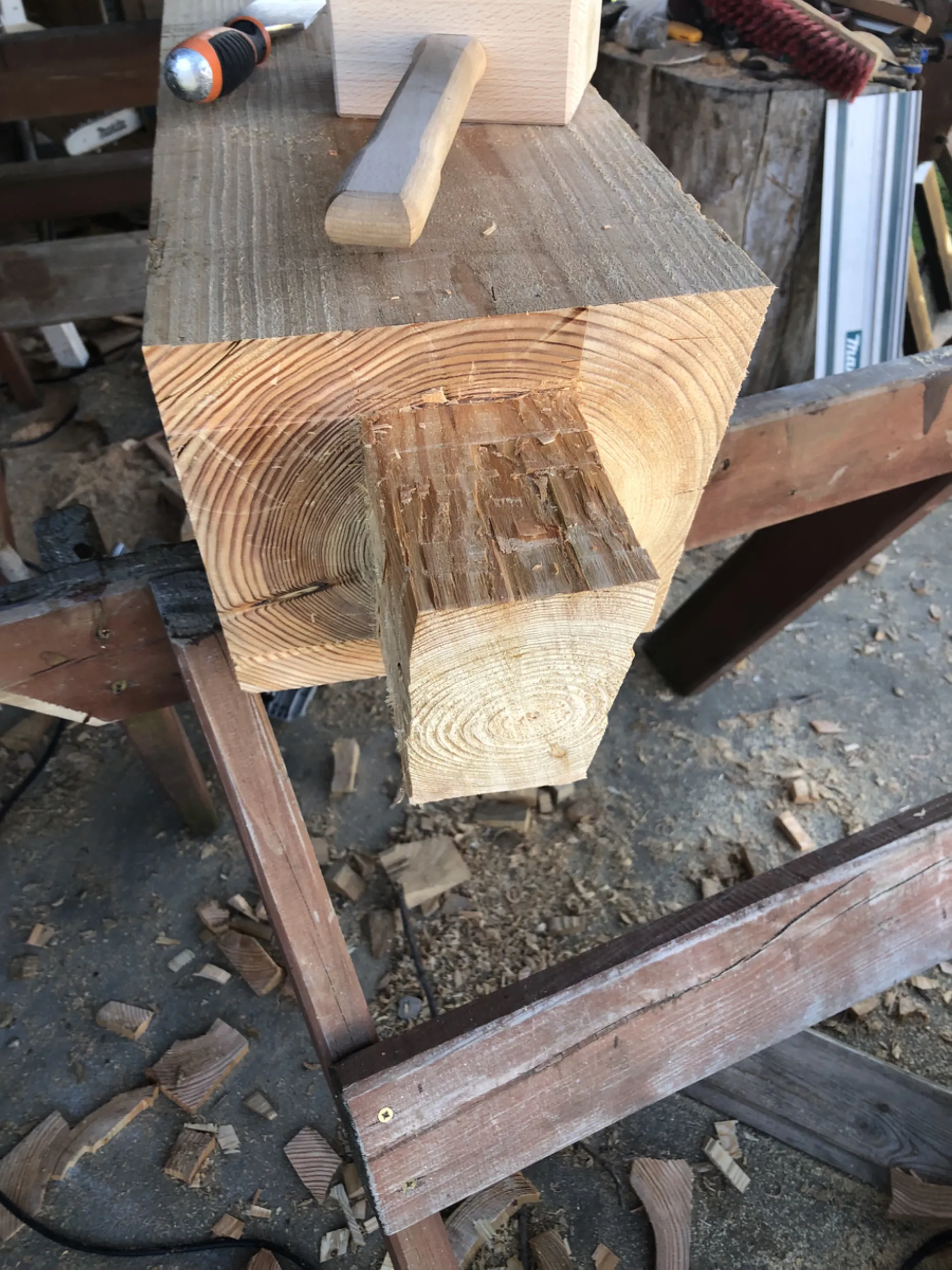
4 – Crafting traditional carpentry joints for the Rurmus structure
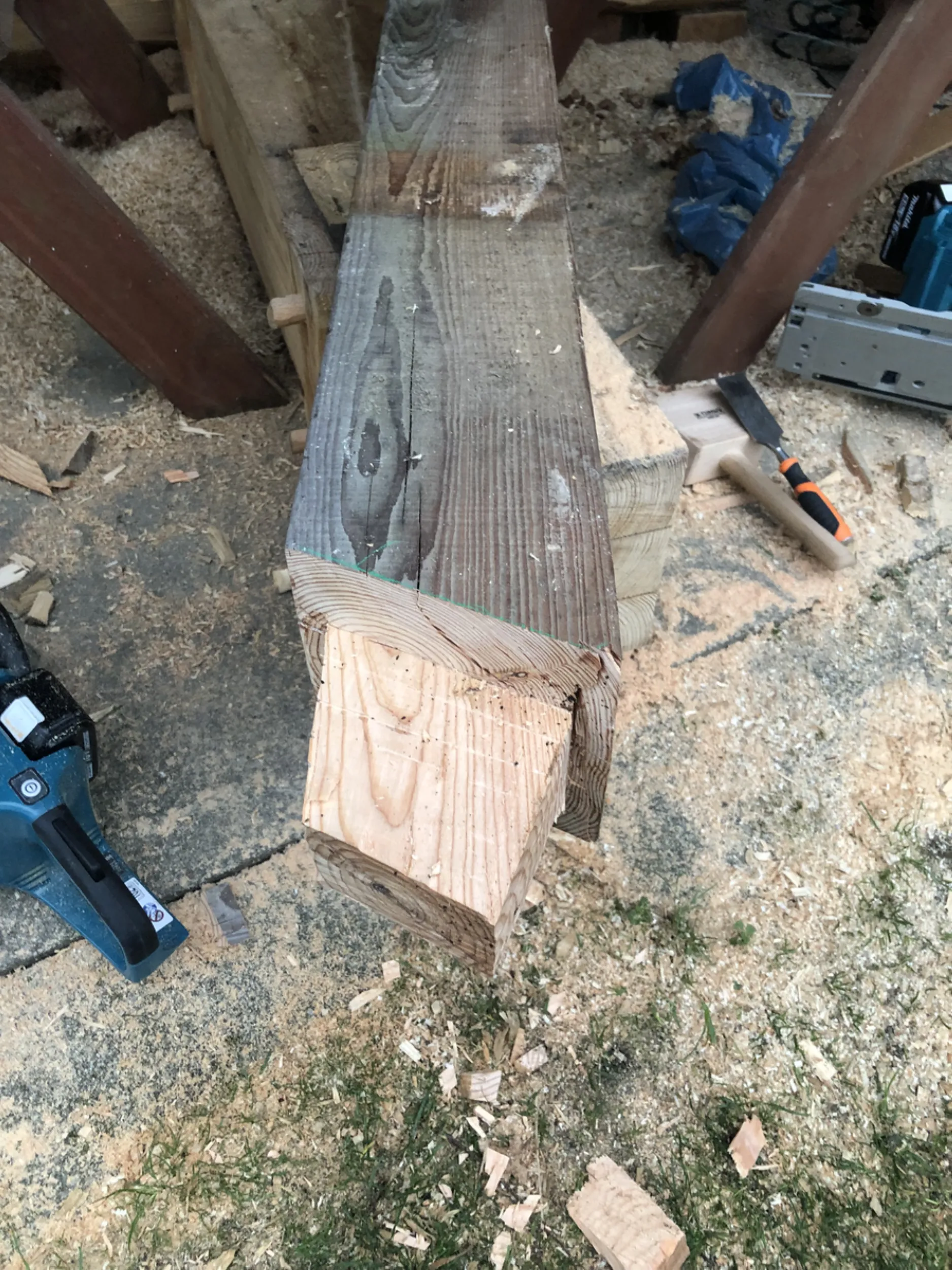
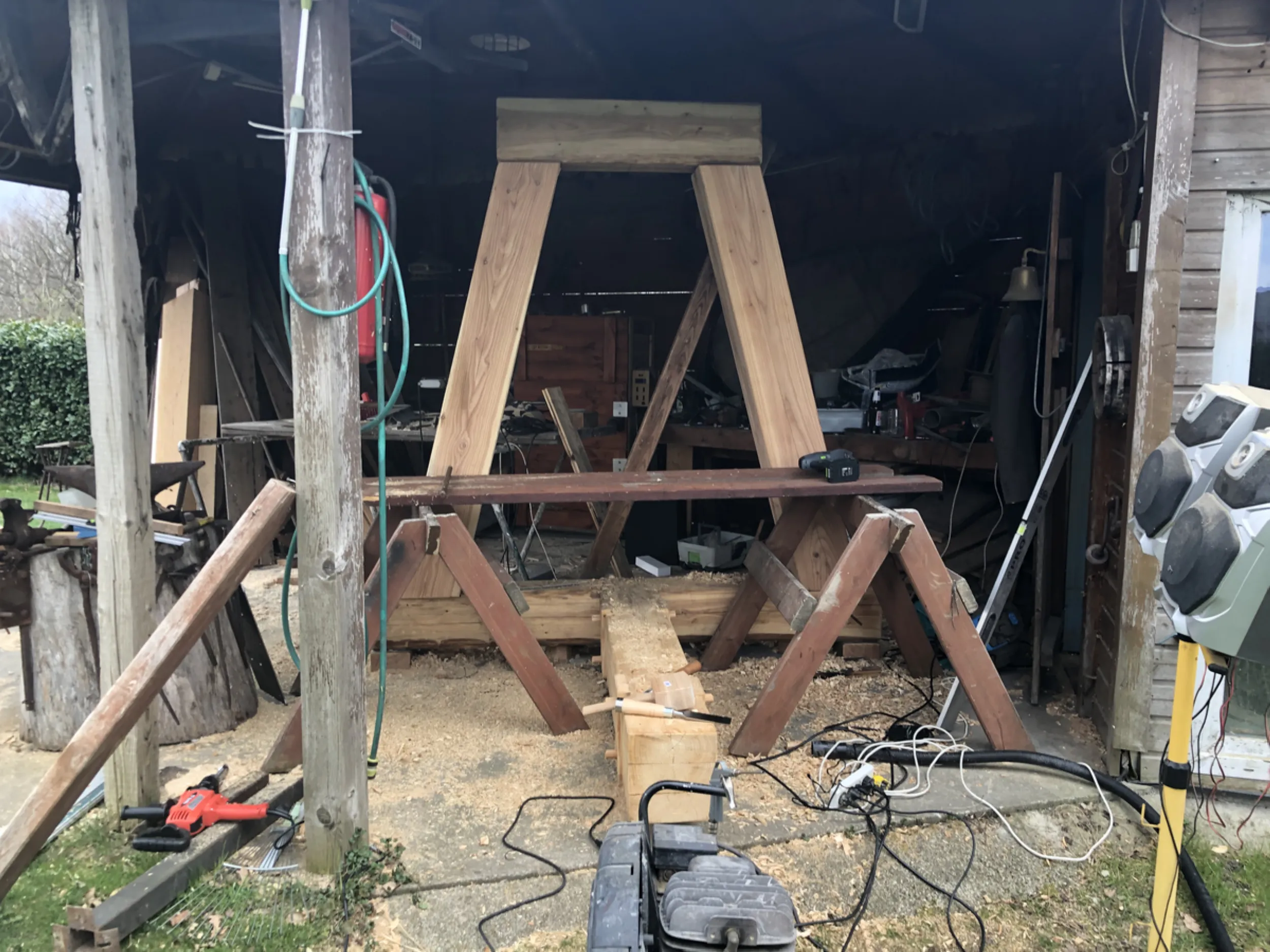
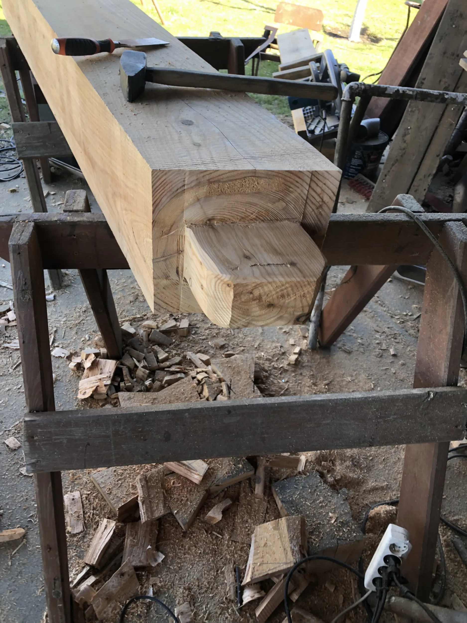
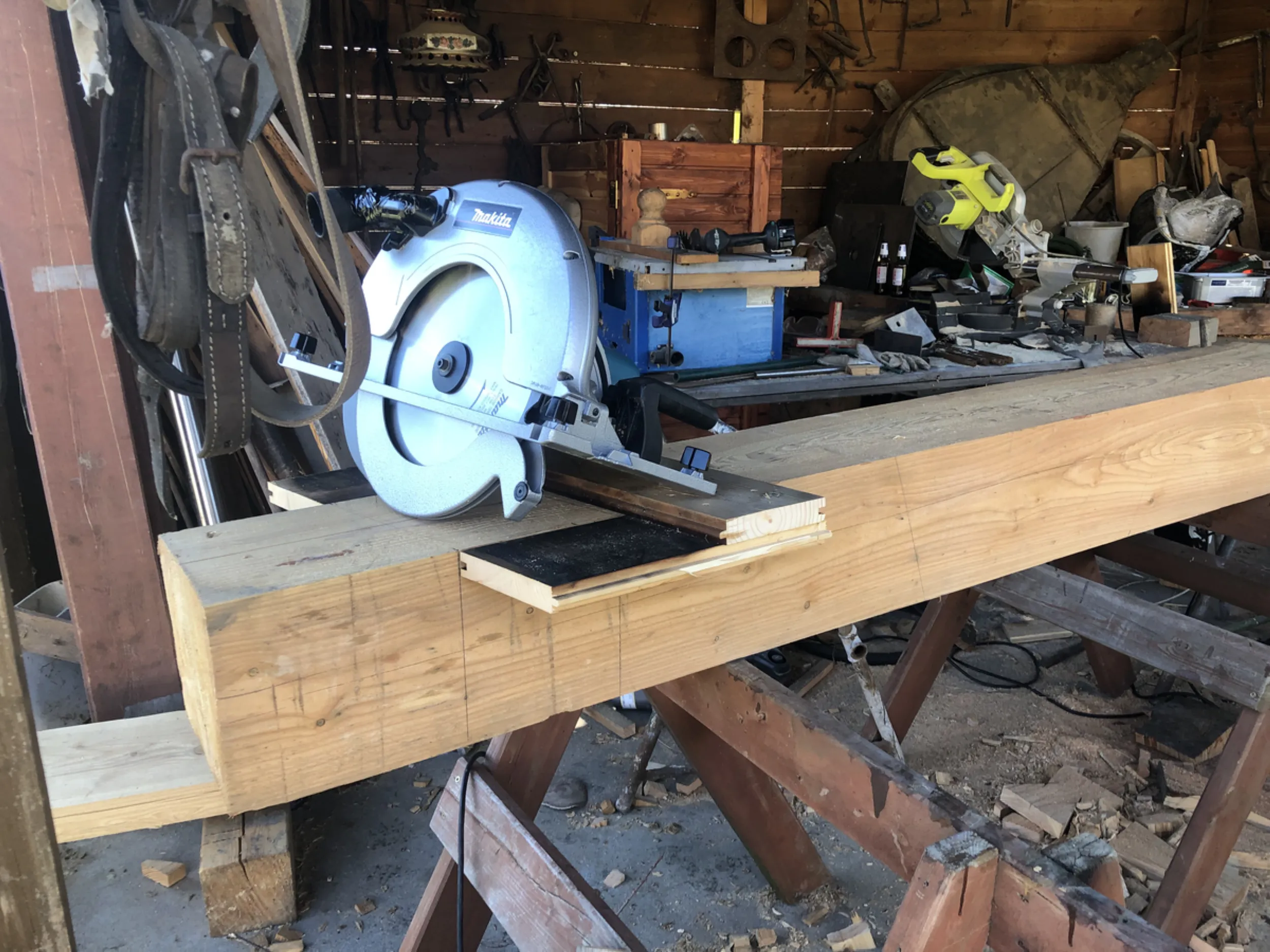
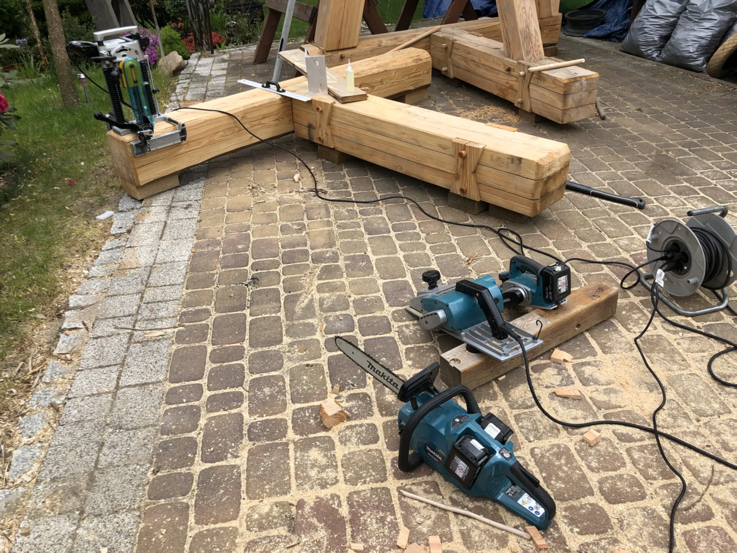
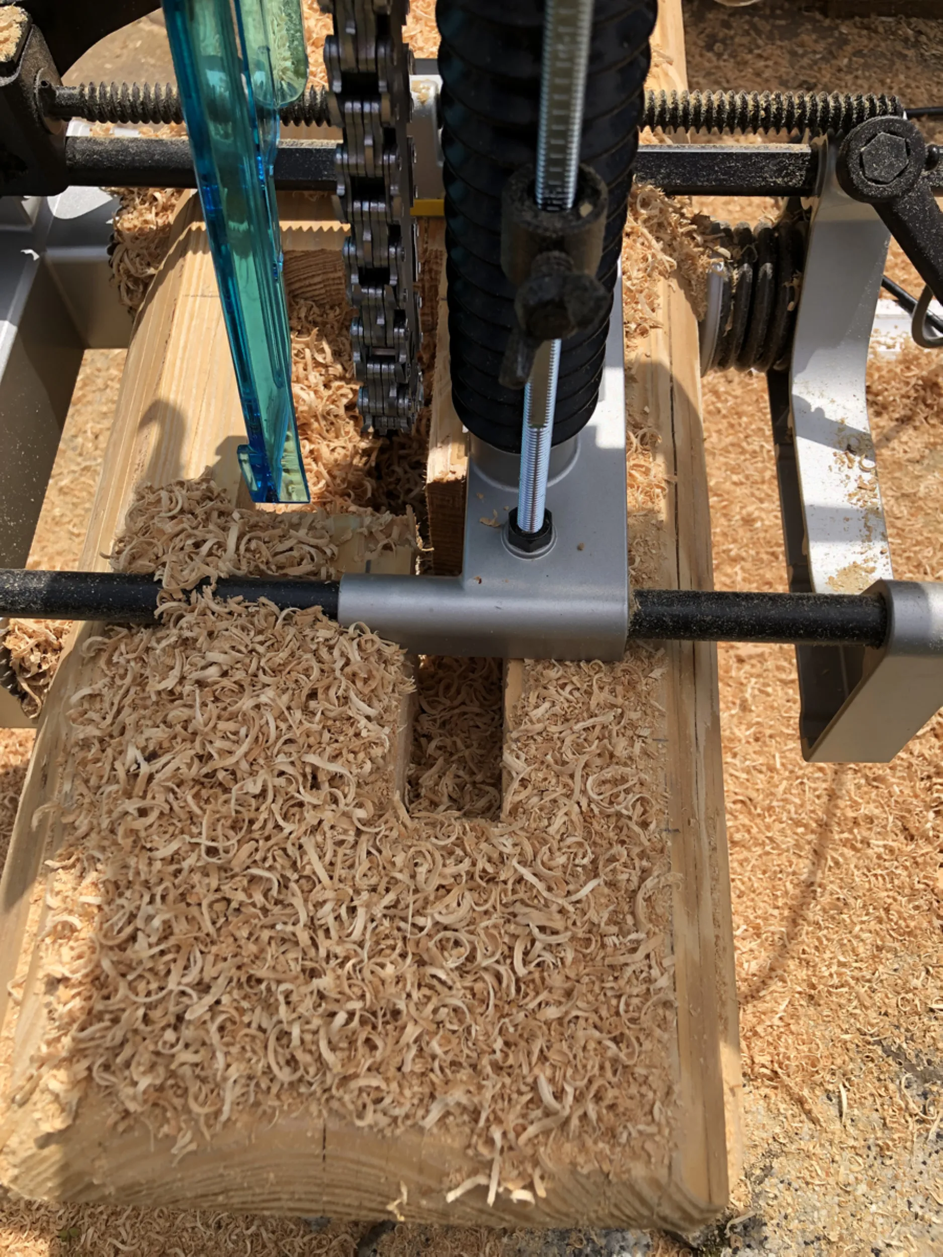
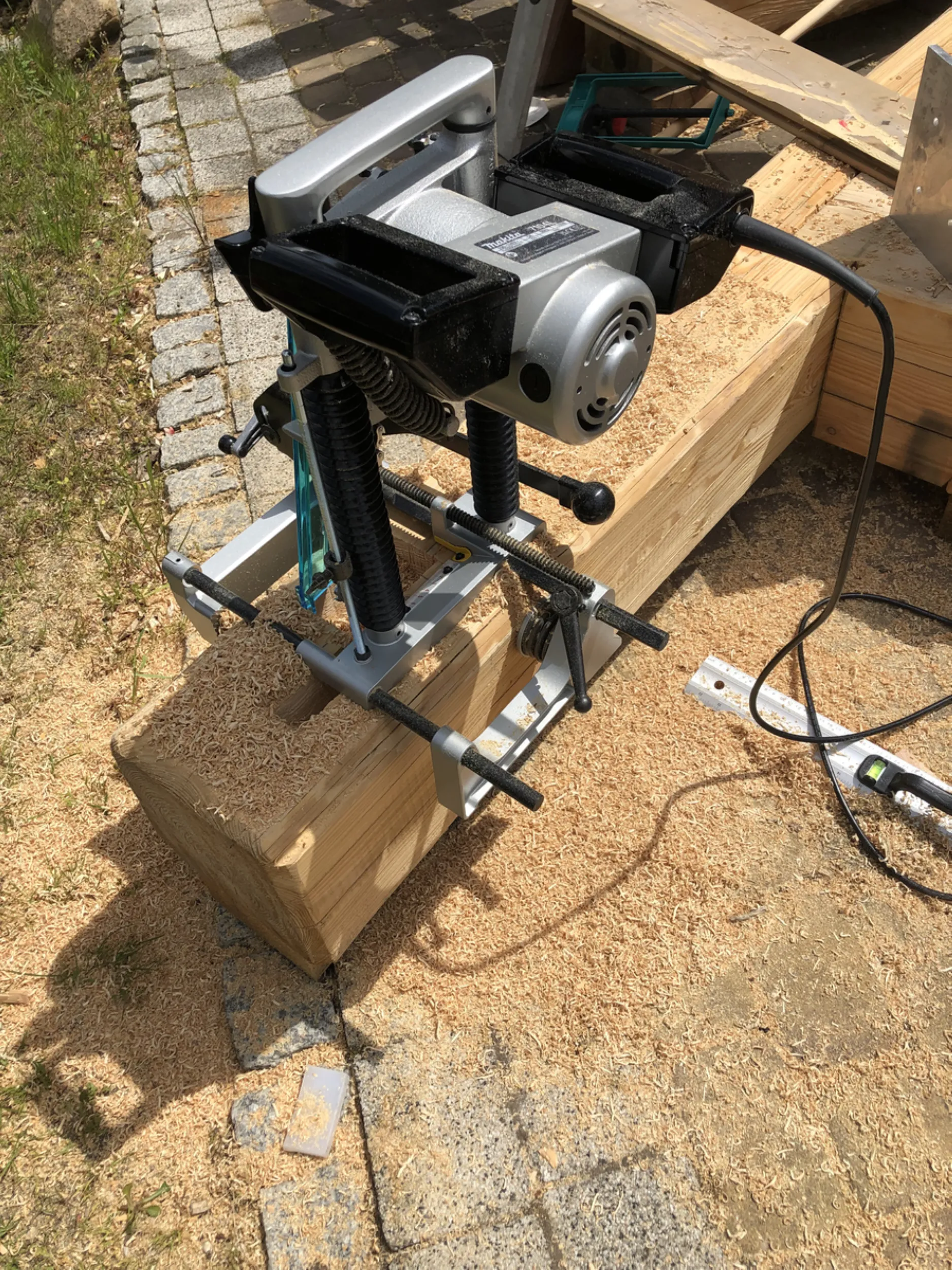
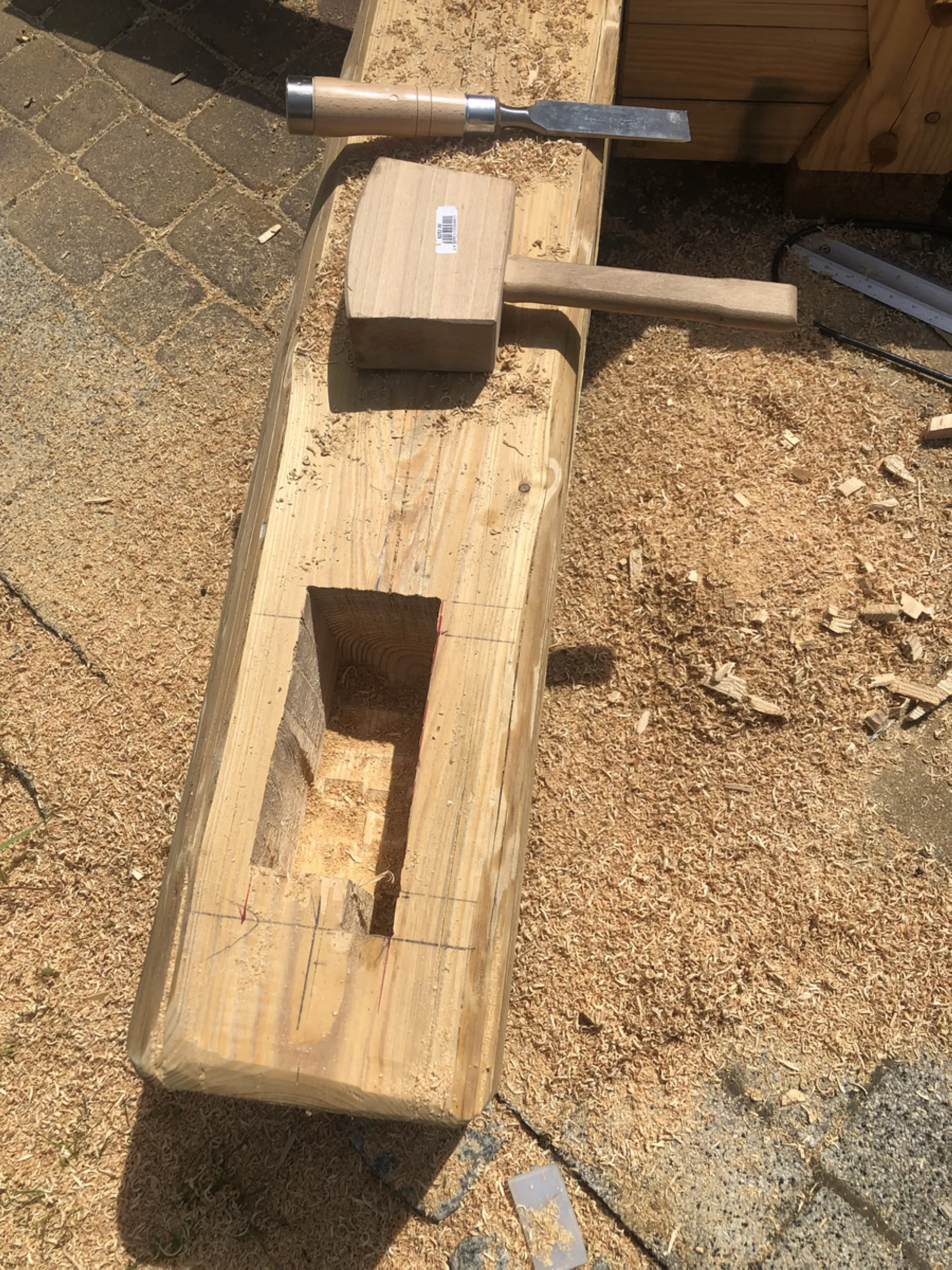
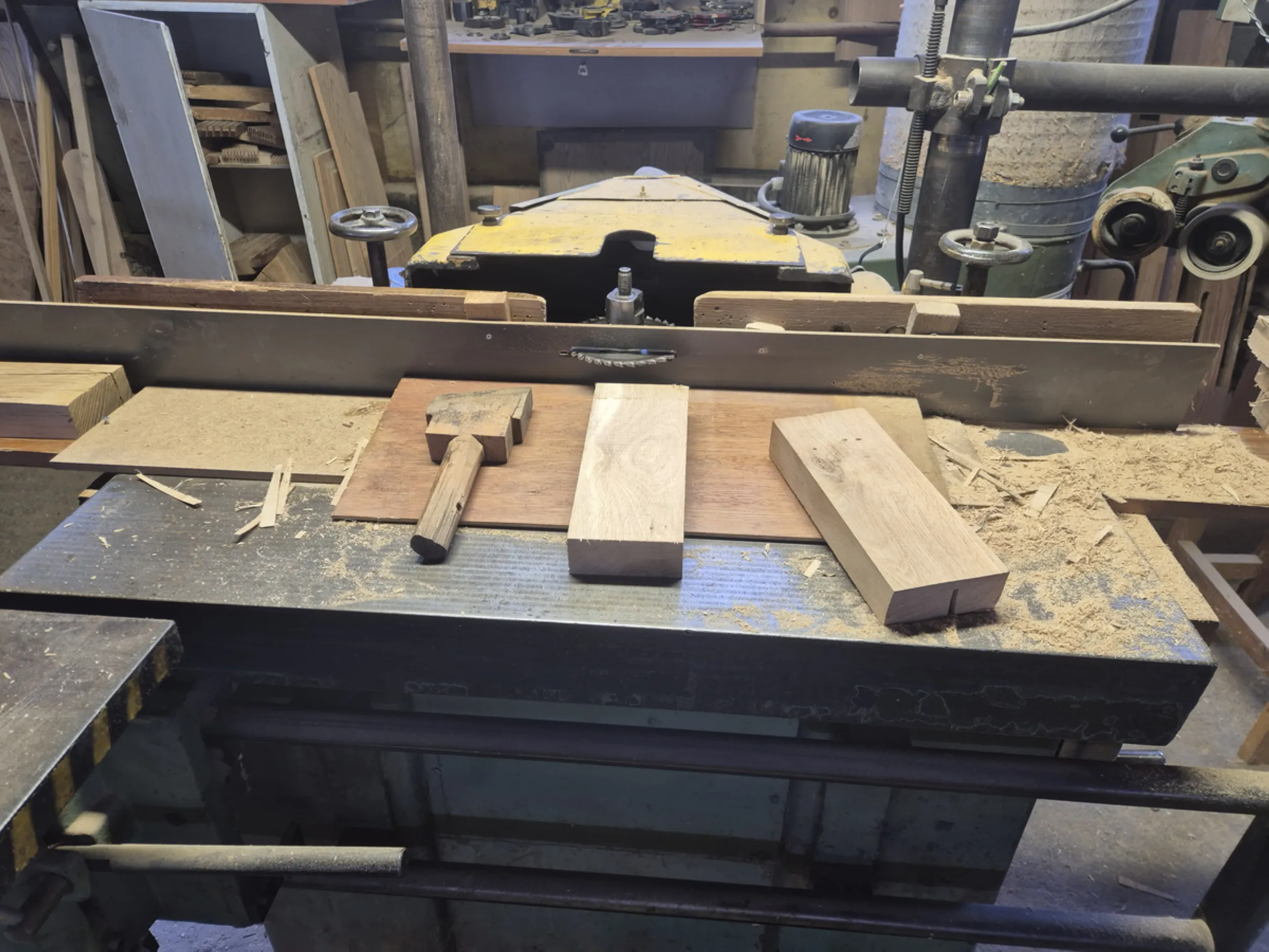
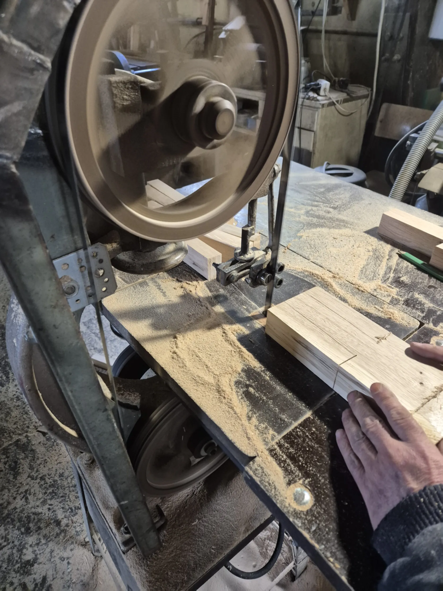
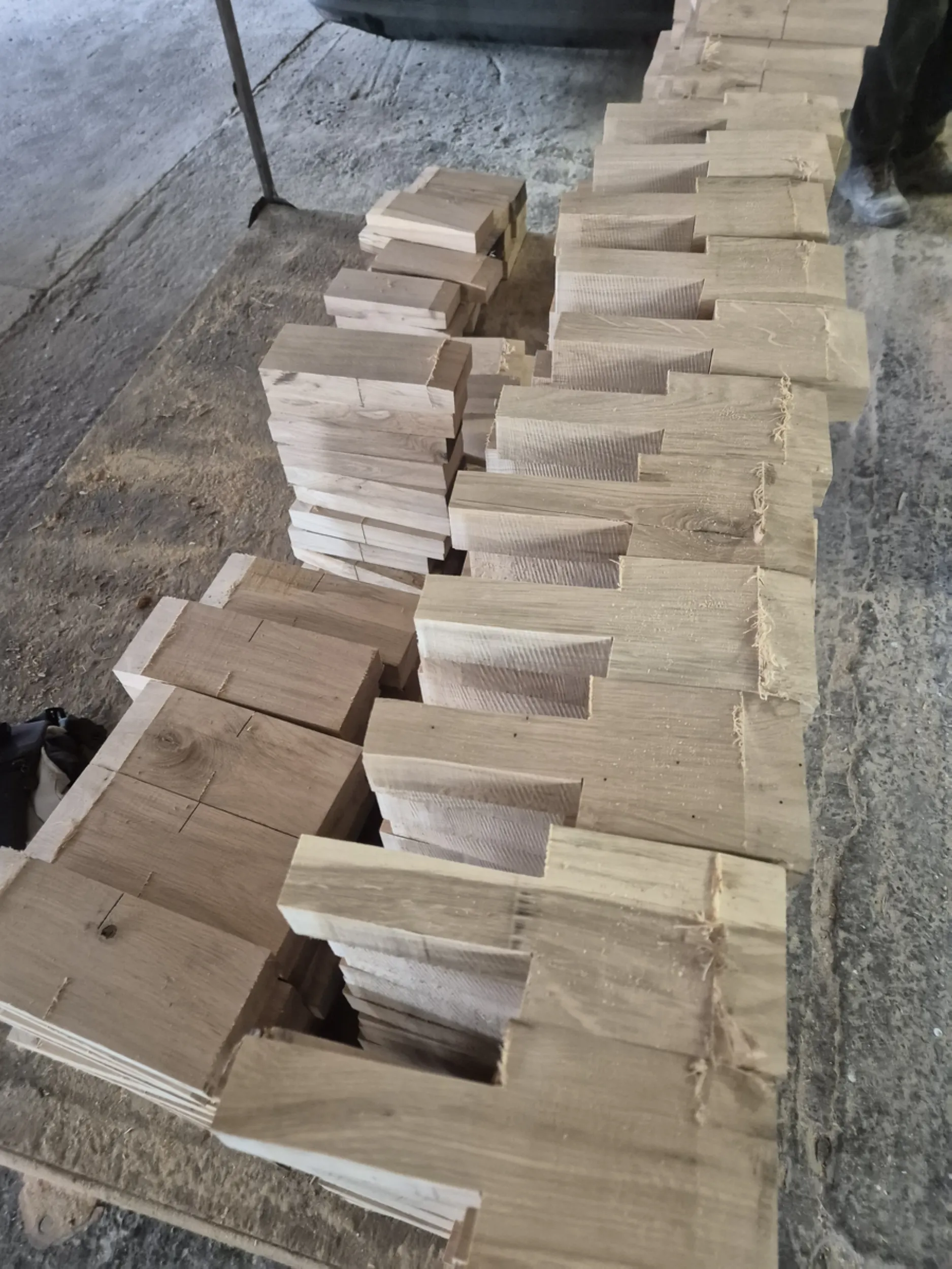
The work focused on preparing the primary carpentry joints that have been used in timber structures for centuries. Tenons, mortises, interlocking notches, and holes for wooden pegs were cut into massive beams; once assembled, these form durable, stable structural connections without relying on modern steel fasteners for load-bearing capacity.
The process involved marking out the timber, manually fitting the contact surfaces, and verifying the precision of each component. Each joint required individual fitting, as even minor deviations could affect the geometry of the entire structure.
This section highlights the craftsmanship involved in building the Rurmus, where traditional carpentry skills play a role just as vital as the technical design. The quality of these joints is what determines the durability, rigidity, and safety of the device’s wooden structure.
- rurmus project -
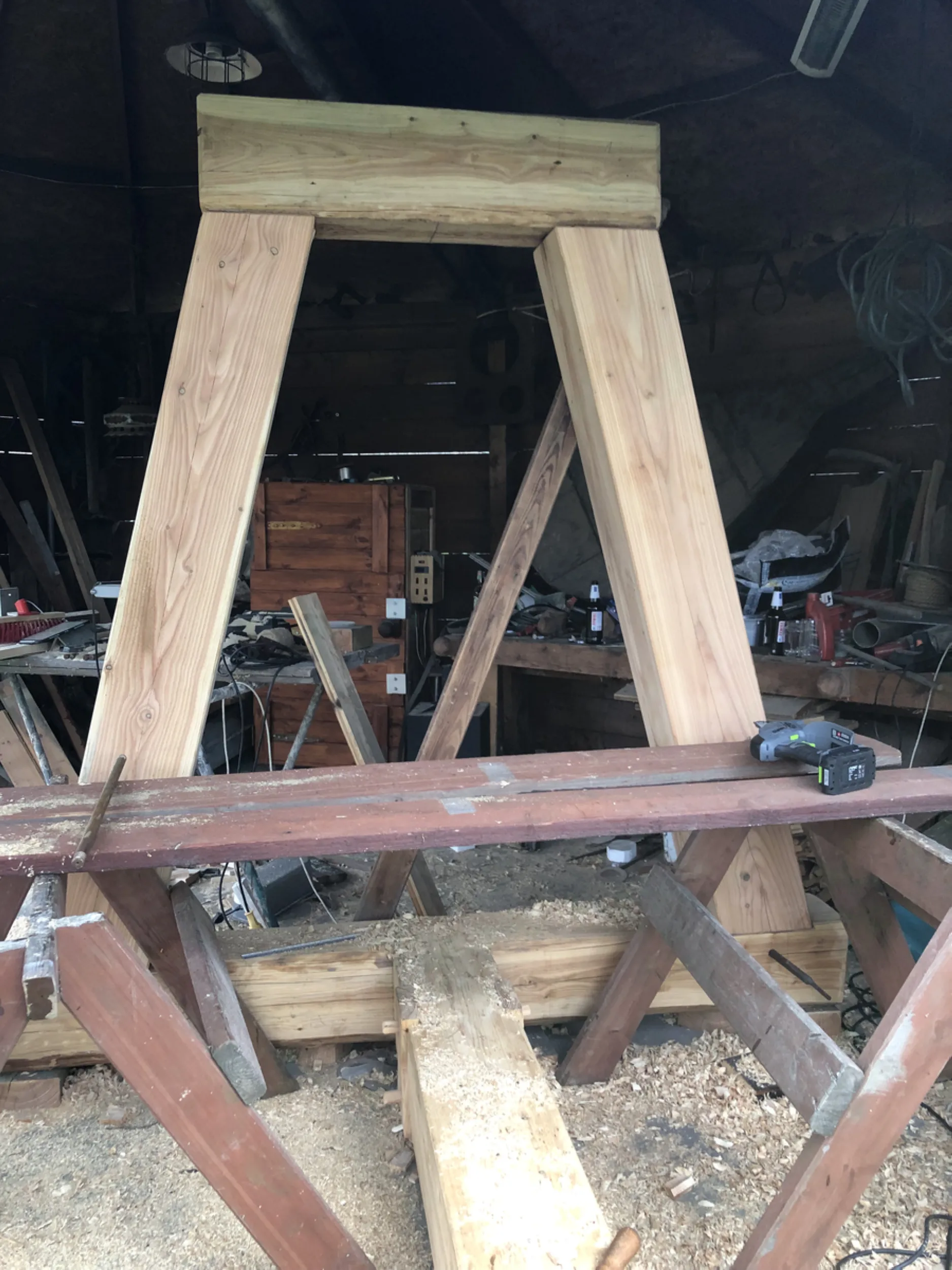
5 – Fabrication and trial assembly of the Rurmus’s main load-bearing structure
Preparing the primary load-bearing elements involved processing massive structural beams, crafting timber joints, and performing a trial assembly of sections of the future tower. Individual posts, girts, and beams were marked out and then fitted to ensure they formed a cohesive structural system upon assembly.
The work shown includes the creation of corner joints, cross-bracing connections, and structural nodes designed to bear the heaviest loads. Each element required repeated dimensional checks, test fittings, and manual adjustment of contact surfaces. This process ensured the precise fit characteristic of traditional timber framing.
The trial assembly made it possible to evaluate the structure’s geometry prior to transport to the construction site. This was the stage where individual beams began to form the actual framework of the future Rurmus, revealing the scale and craftsmanship of the entire timber structure.
- rurmus project -
6 – Fabrication of components for the Rurmus wooden drive transmission
The work involved fabricating parts of the mechanism responsible for transmitting power between the water wheel and the other components of the device. Structural elements of the transmission were crafted from solid wood, requiring high dimensional accuracy and precise fitting of all working surfaces.
The process included marking out, machining, and fitting the mechanical parts that interact during the device’s operation. Each component was crafted individually, with its shape determined directly by the function it was to perform within the drive system. Precision was of particular importance, as even minor deviations could affect the smooth operation of the entire mechanism.
The resulting components exemplify a blend of traditional carpentry and historical water-powered machinery construction techniques. It is at this stage that the wooden structure begins to transform into a functional mechanism capable of transmitting energy and performing work.
- rurmus project -
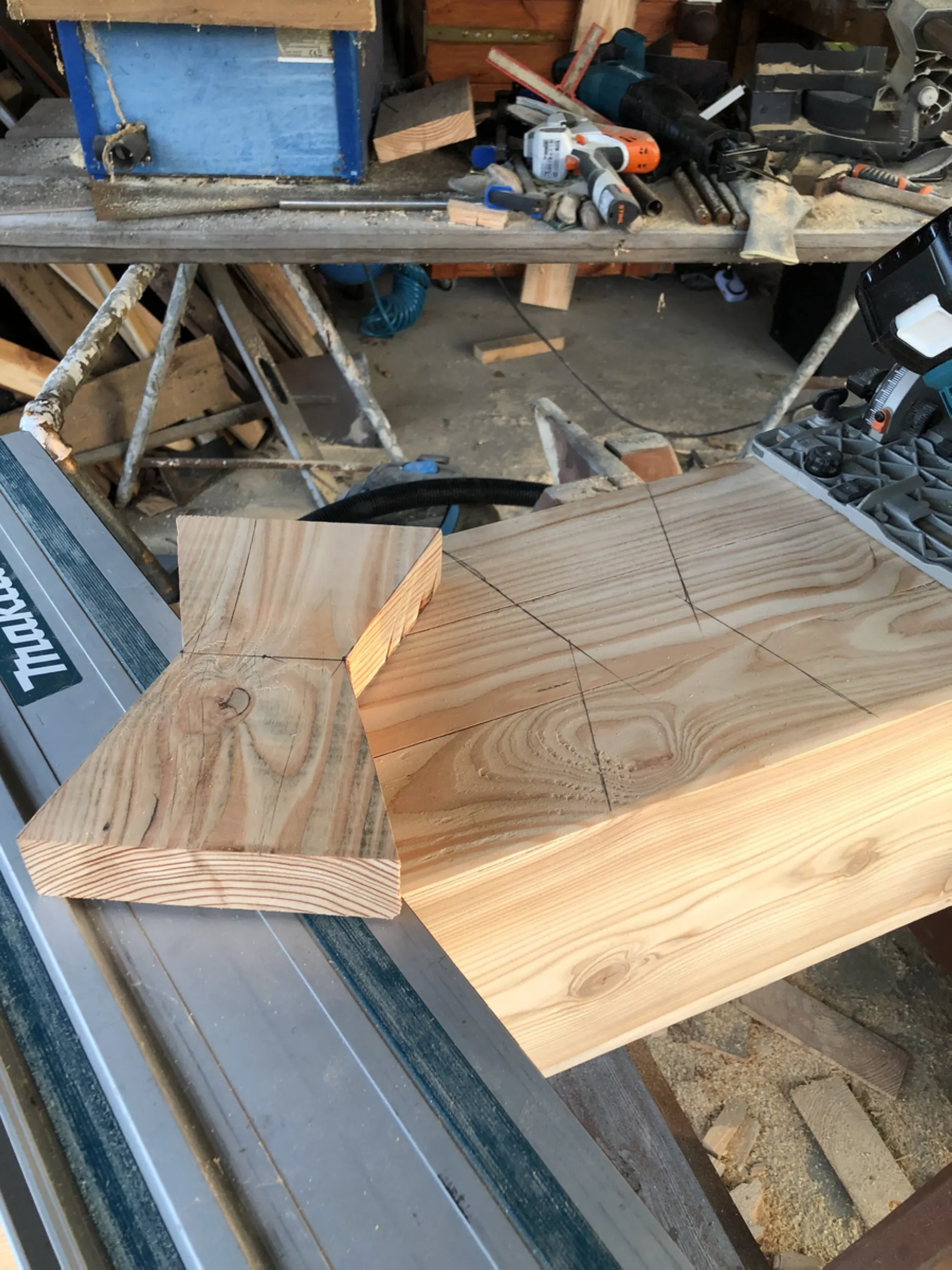
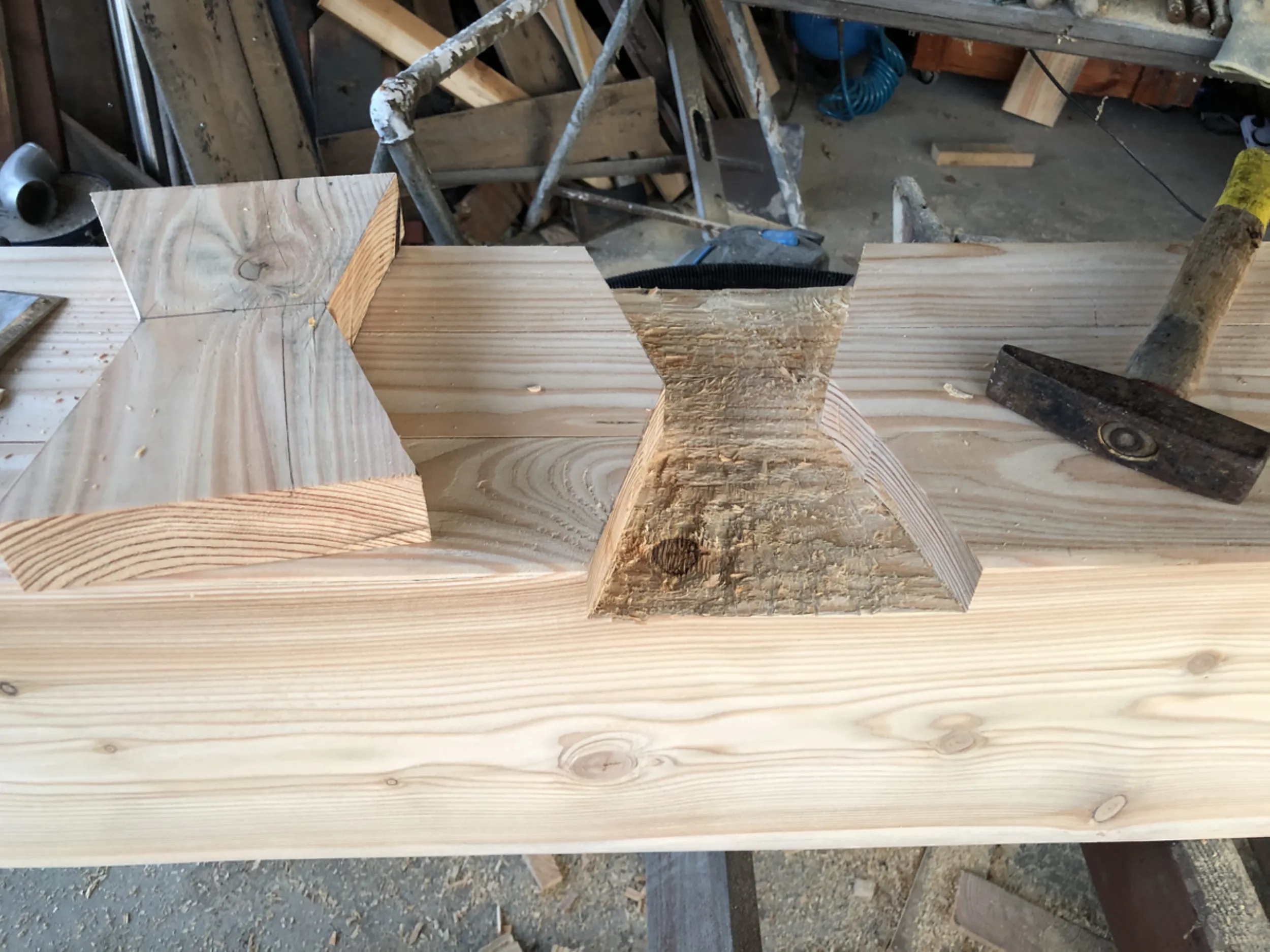
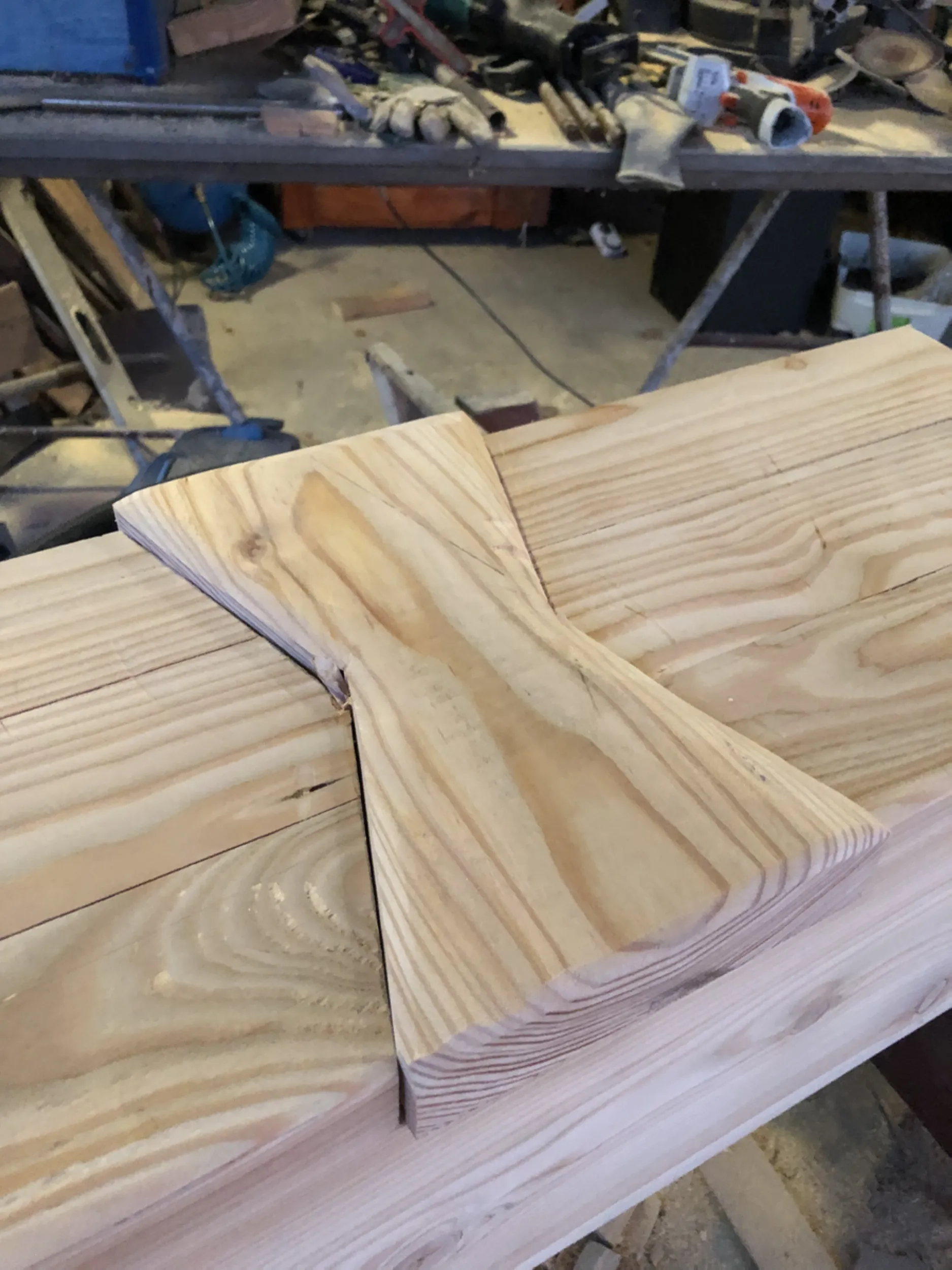
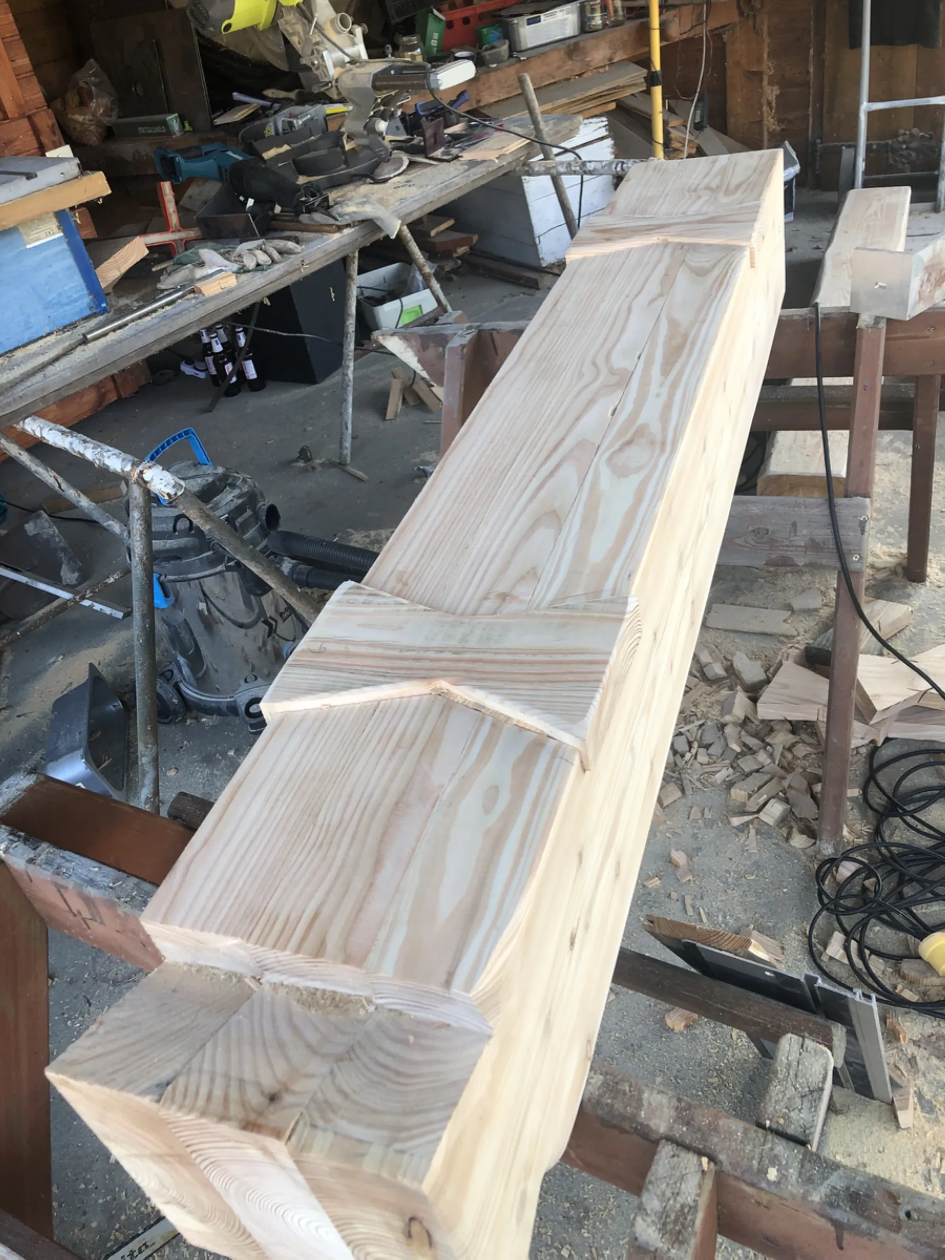
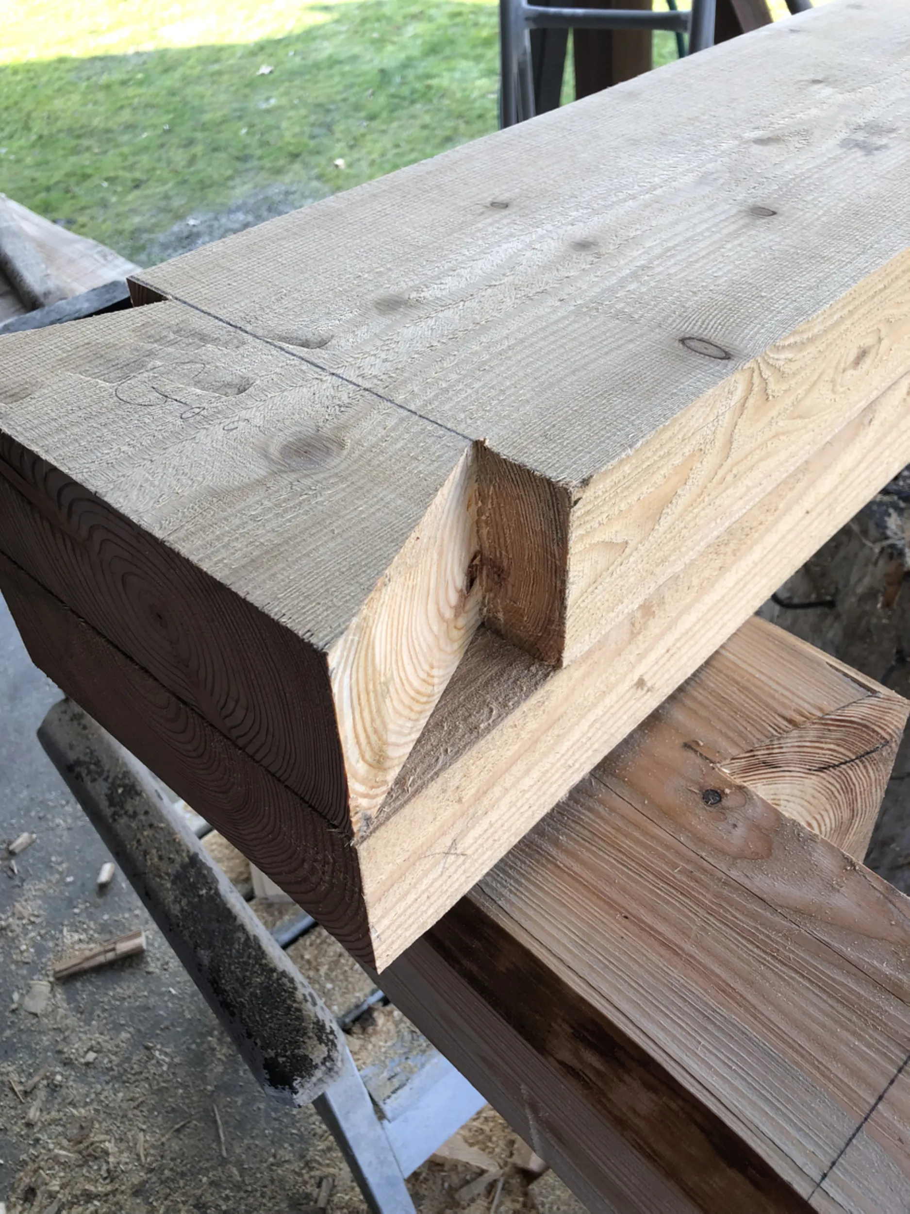
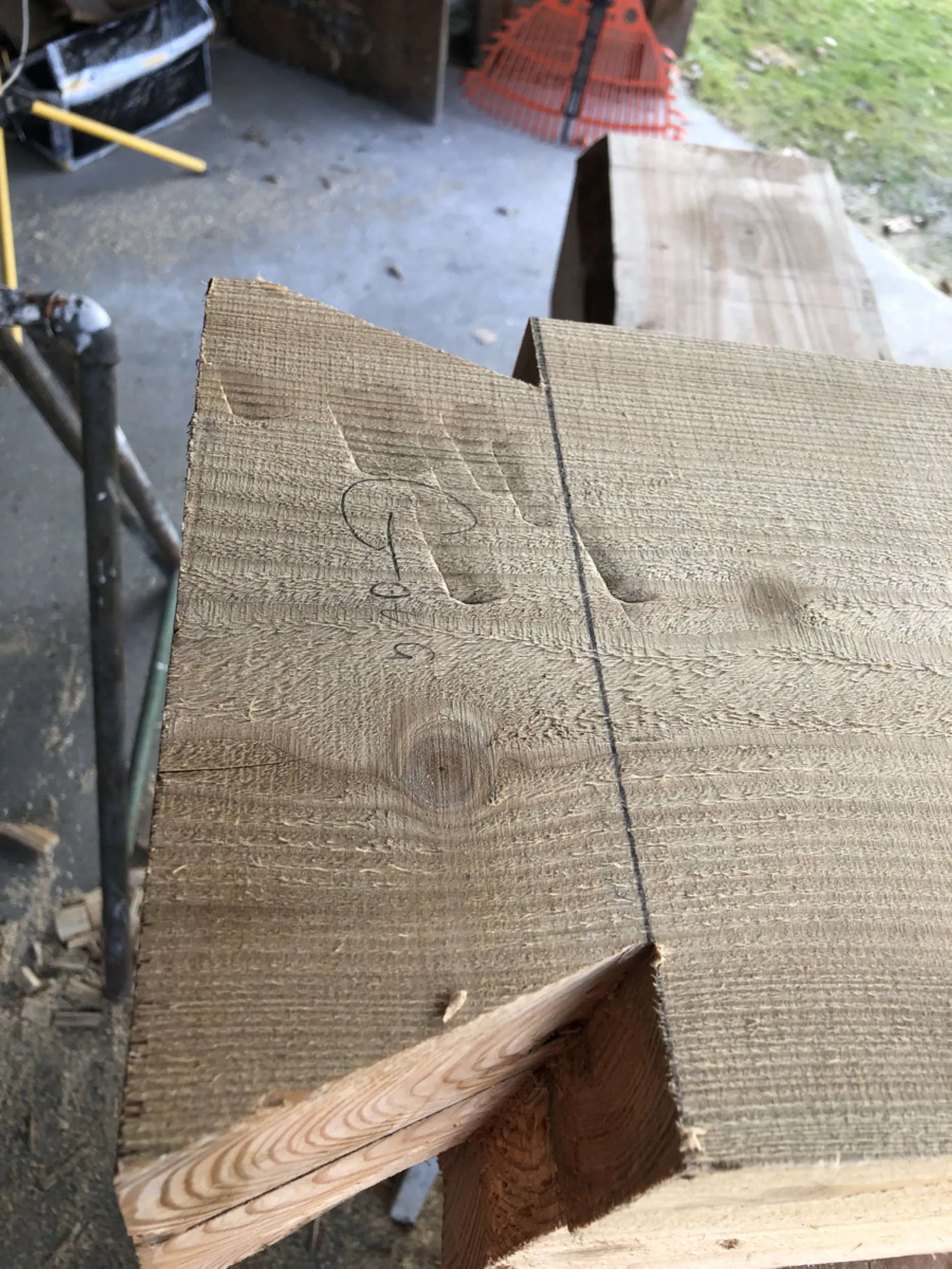
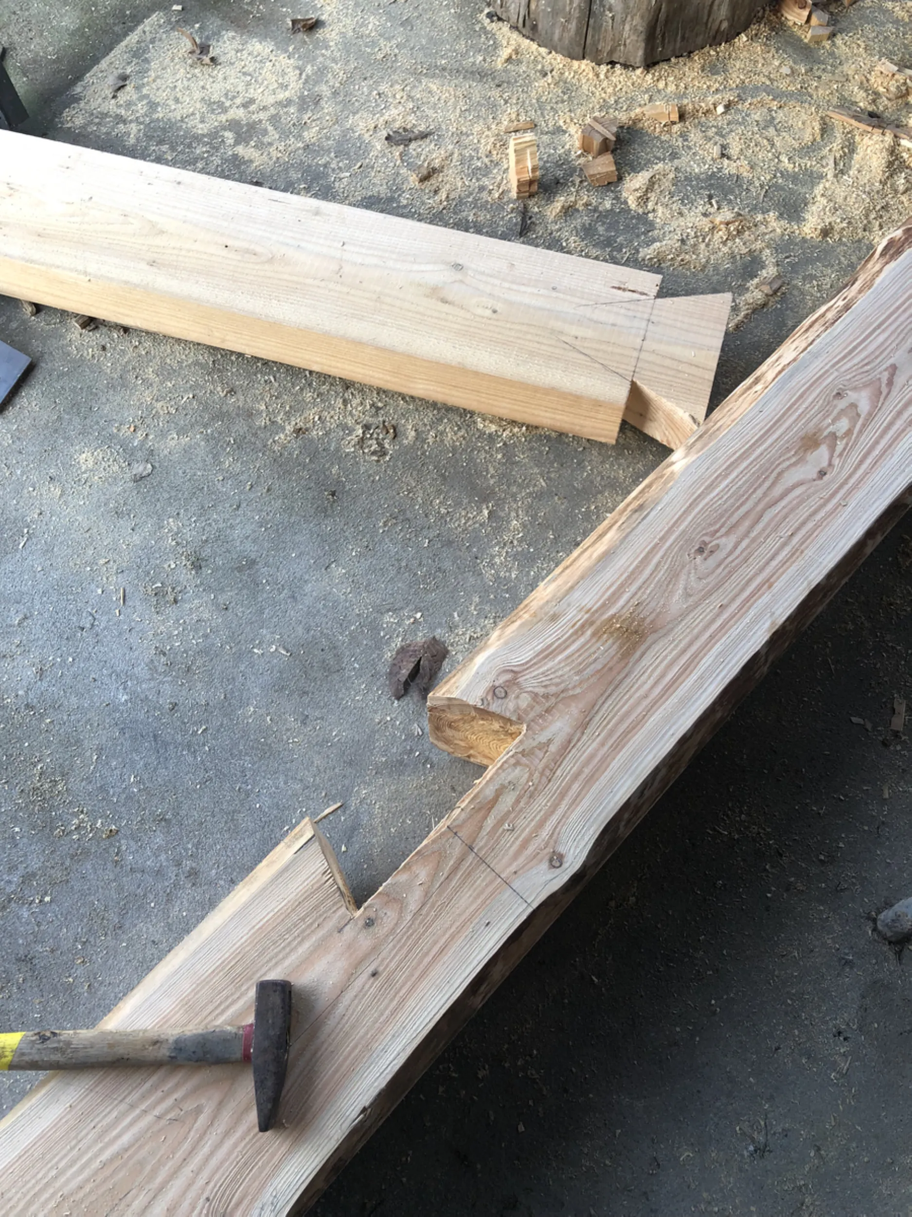
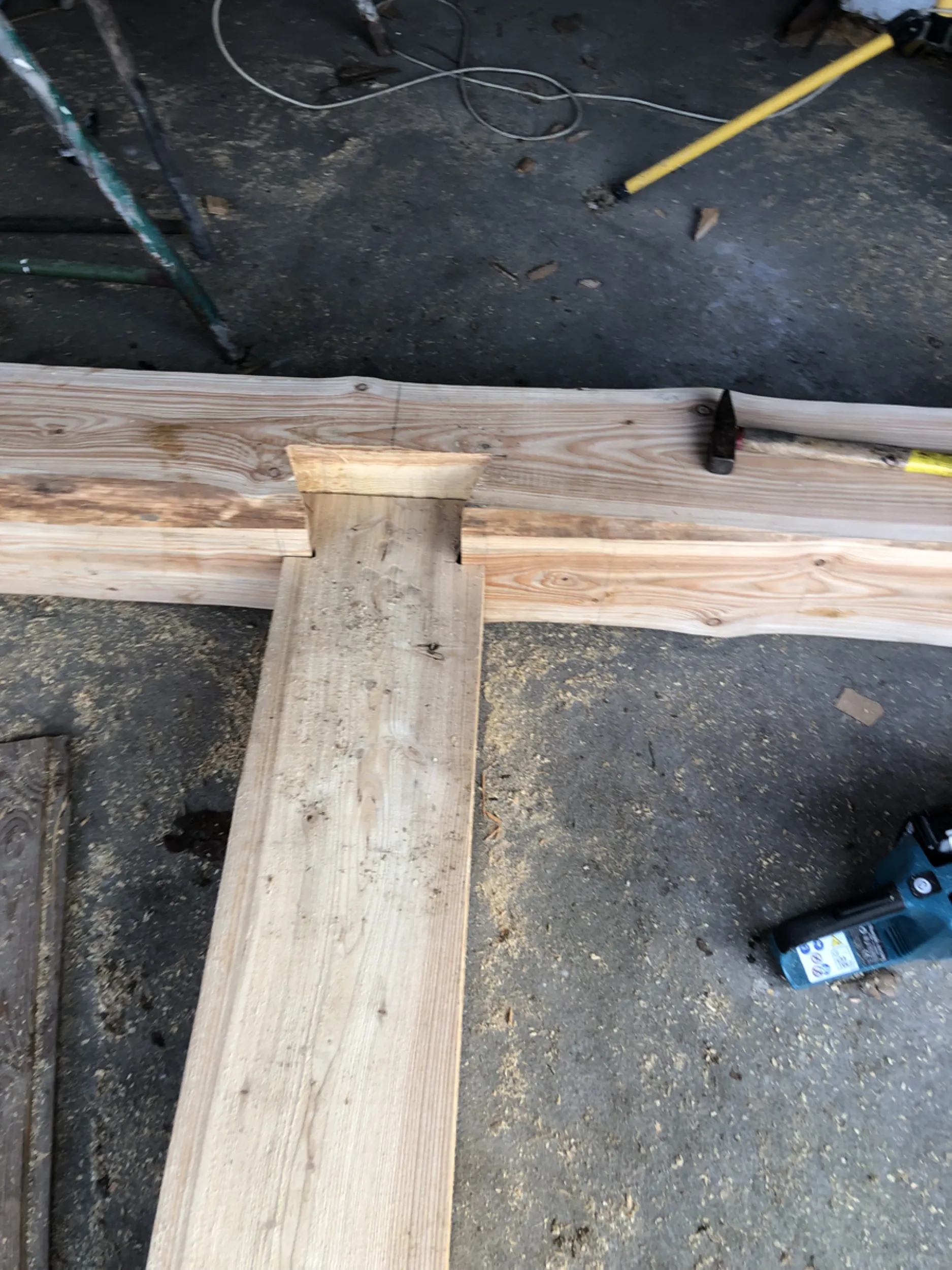
7 – Traditional Dovetail Carpentry Joints
The work shown here illustrates one of the most demanding aspects of traditional carpentry: the crafting of dovetail joints. The joint’s distinctive shape causes the components to lock together upon assembly, creating a durable and stable structural connection without the need for metal fasteners as the primary load-bearing elements.
Each joint required individual layout, precise marking of cut lines, and repeated fitting of the mating surfaces. The quality of the joint depended on the accuracy of the woodworking and the carpenter’s experience, as even minor deviations affected the structural performance of the entire assembly.
Joints of this type have been used for centuries in the construction of mills, bridges, granaries, and other large timber structures. They exemplify a craft in which structural integrity relied primarily on the geometry of the joint and the skill of the craftsman.
- rurmus project -
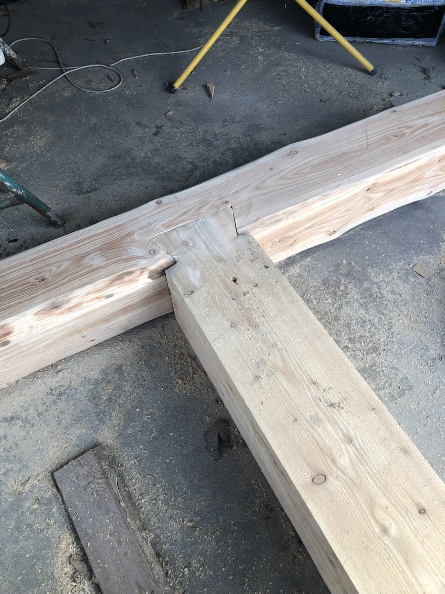
8 – The Rurmus Tower’s Main Structural Joint
A central element of the work described here is the creation of one of the tower’s most critical structural connections. The joint between the crossbeam and the main horizontal beam utilizes the traditional dovetail geometry—a technique employed for centuries in timber construction where high strength and stability are required.
Crafting this joint demanded precise layout work, the maintenance of exact angles, and repeated test-fitting of the components. The joint’s distinctive shape causes the beams to wedge together automatically, resulting in a highly rigid structure while preserving the traditional craftsmanship.
This work showcases the artistry of historical carpenters, for whom precision in woodworking was just as vital as the structural design itself. Such joints were the foundation of the durability found in mills, granaries, and other large-scale timber structures.
- rurmus project -
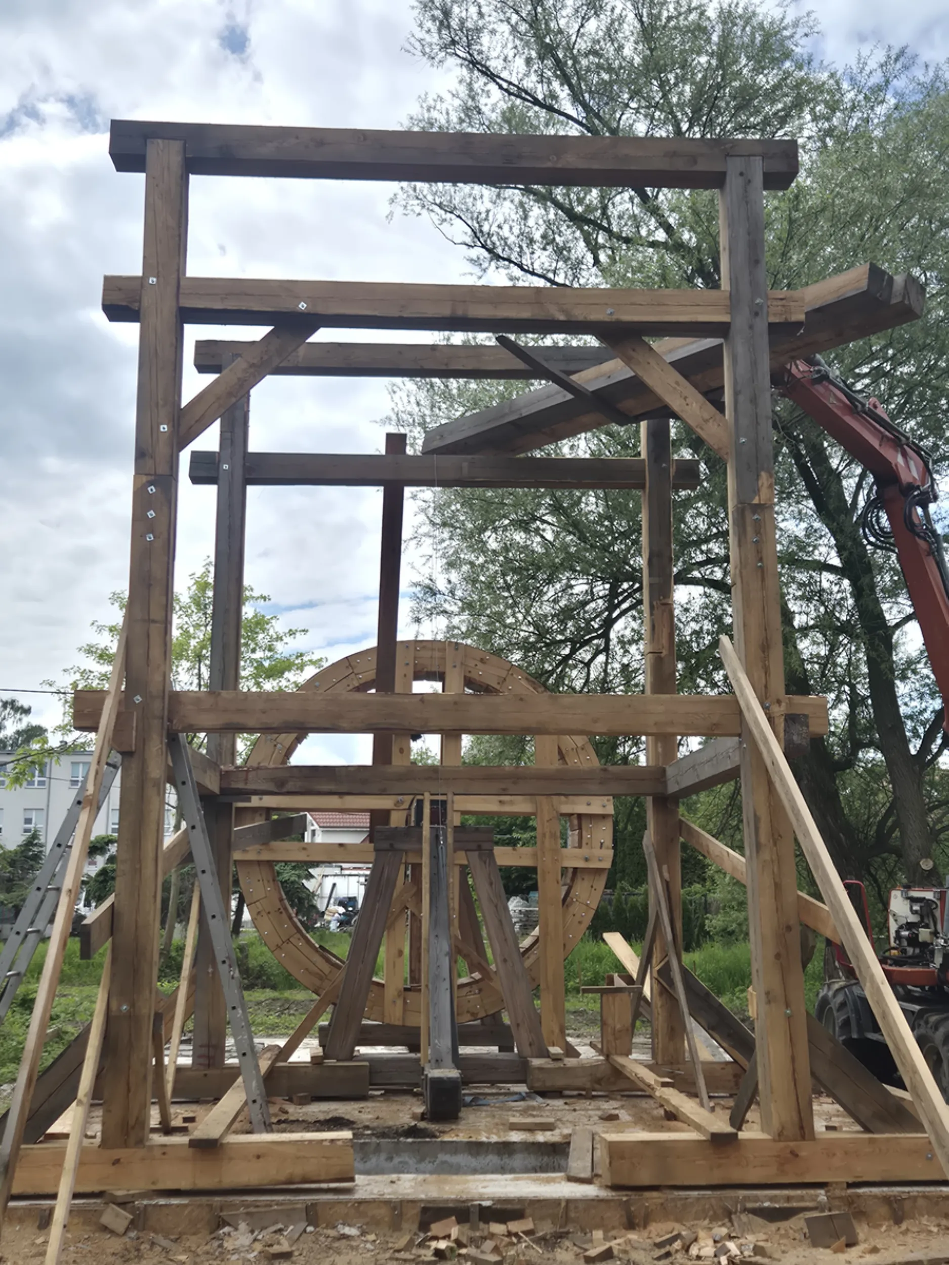
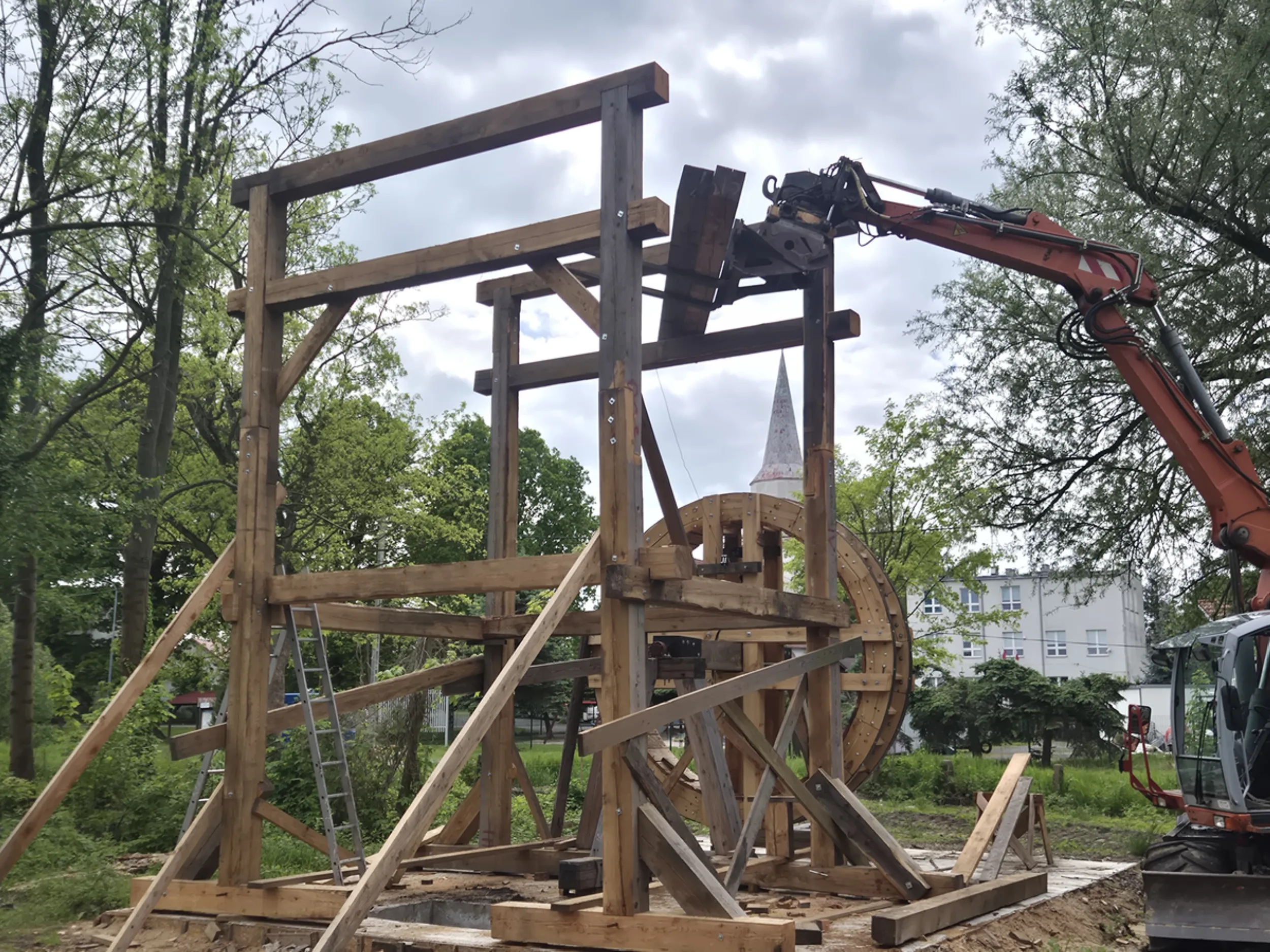
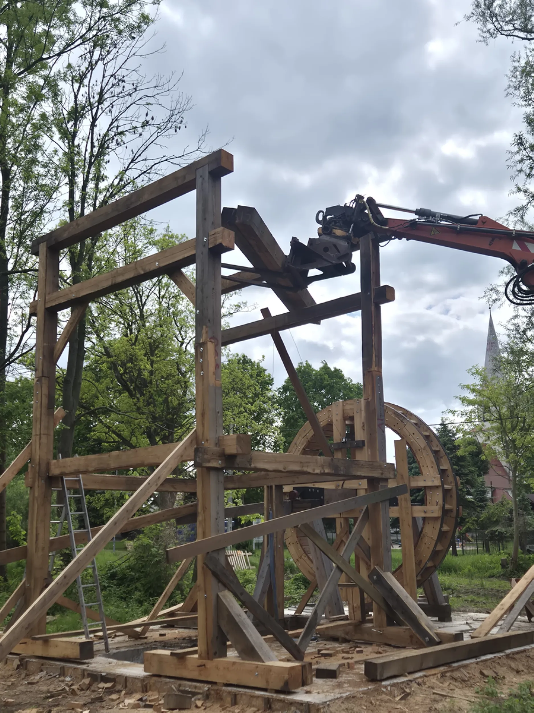
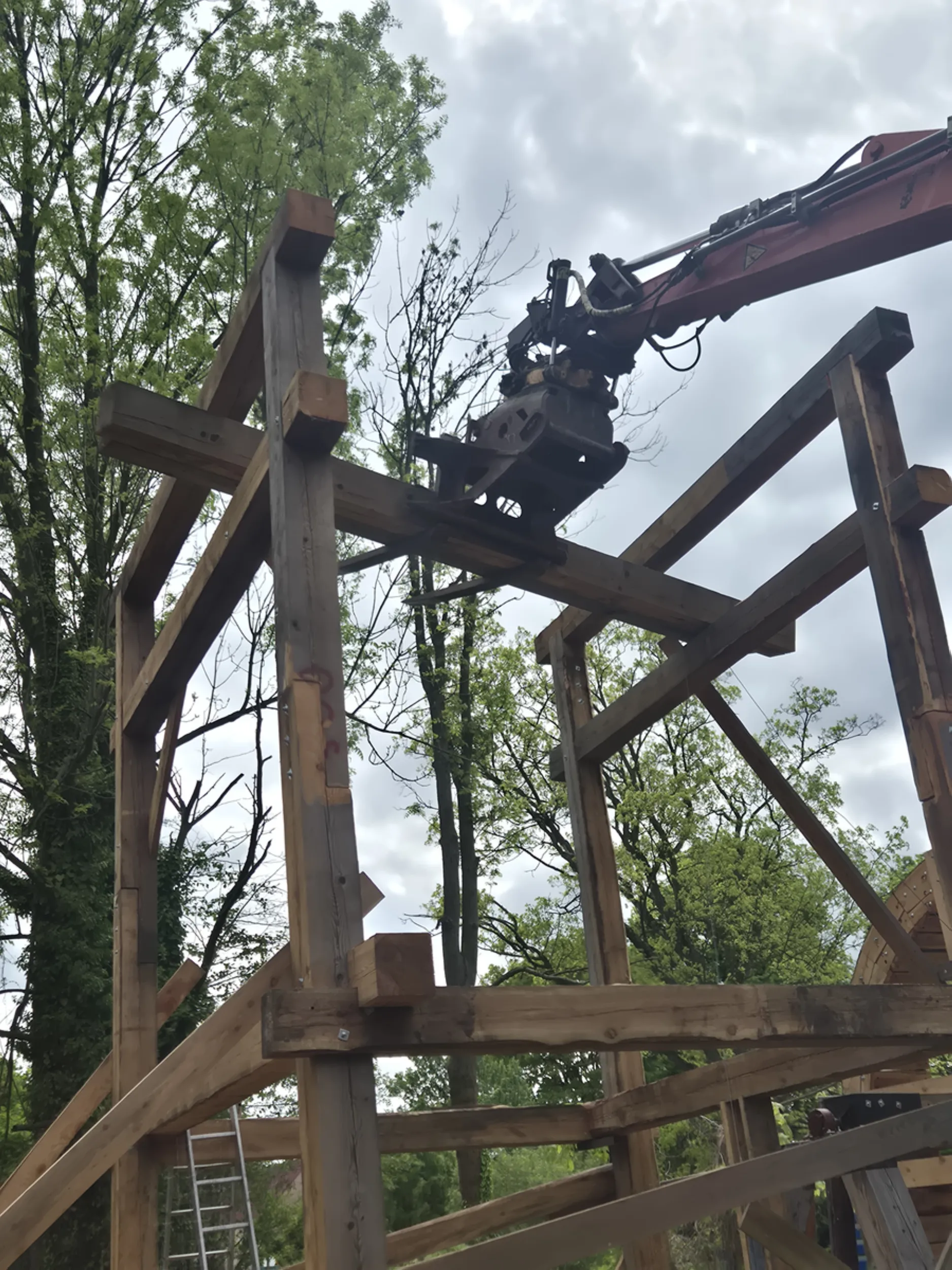
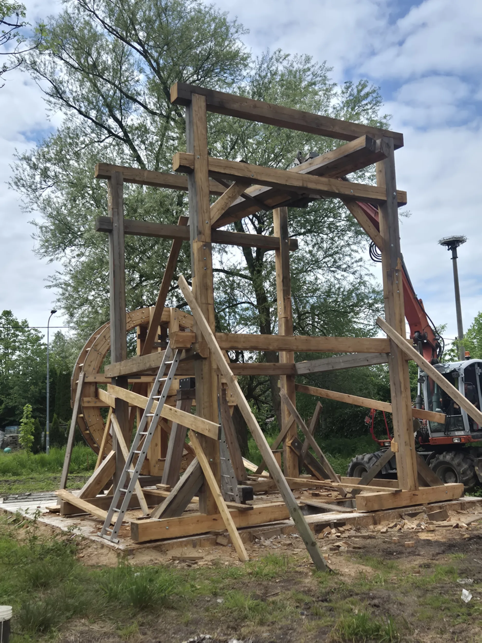
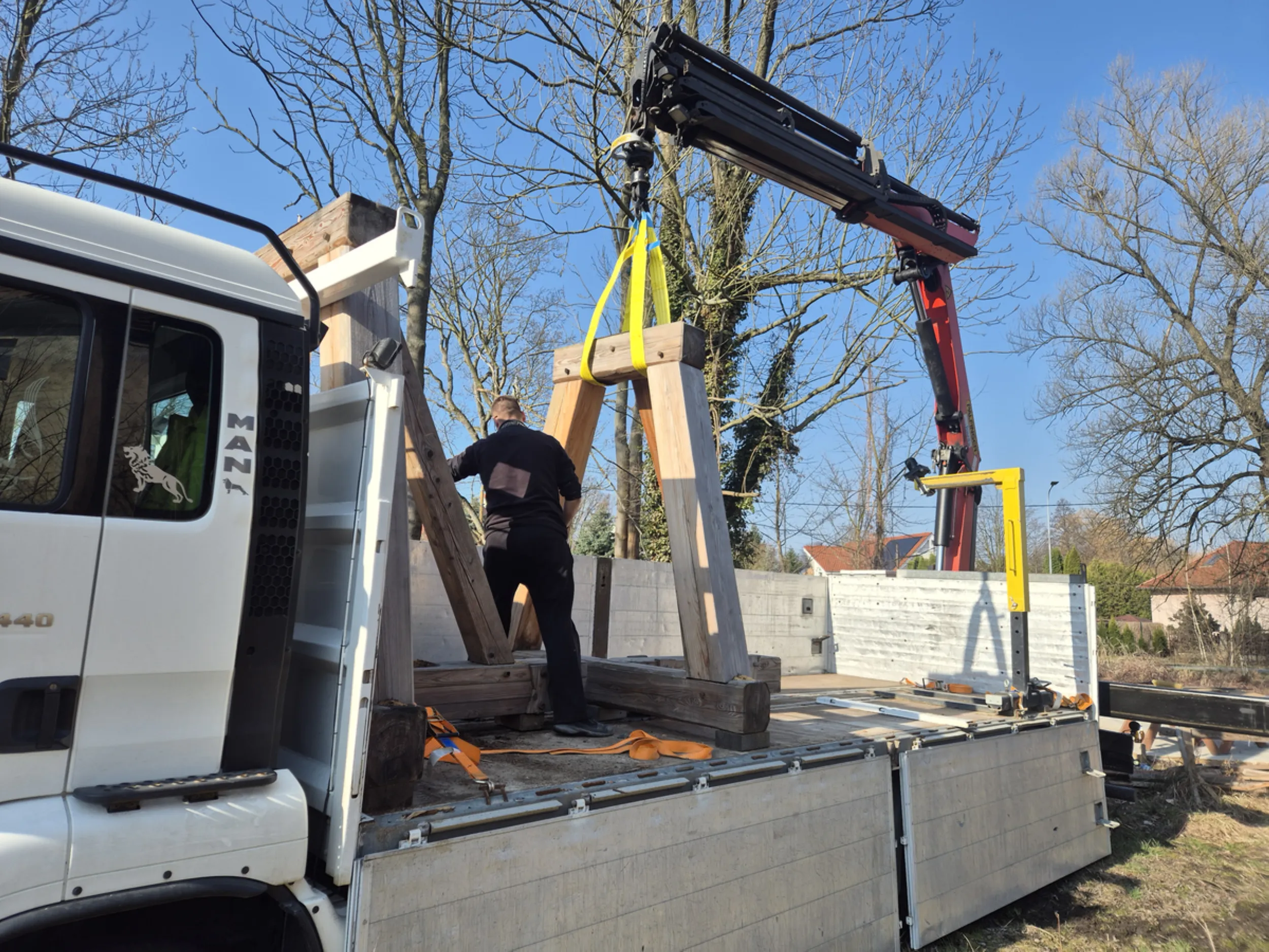
9 – Erecting the wooden Rurmus tower
The images show the moment when individual beams begin to form the full-scale structure of the Rurmus. Massive posts, crossbeams, and bracing elements have been joined into a spatial framework that serves as the skeleton of the future tower. Given the size and weight of the individual components, mechanical equipment was required to lift and position them safely and precisely.
The structure was assembled using pre-prepared carpentry joints; the precision of these joints was crucial for the proper fit of the entire assembly. Temporary assembly braces are also visible, stabilizing the components until the structure was fully integrated into a single unit.
This stage marks the point where traditional carpentry meets the scale of historic hydraulic engineering. The rising tower forms the core of the device—housing the water-lifting mechanism—and gives the Rurmus its distinctive silhouette.
- rurmus project -
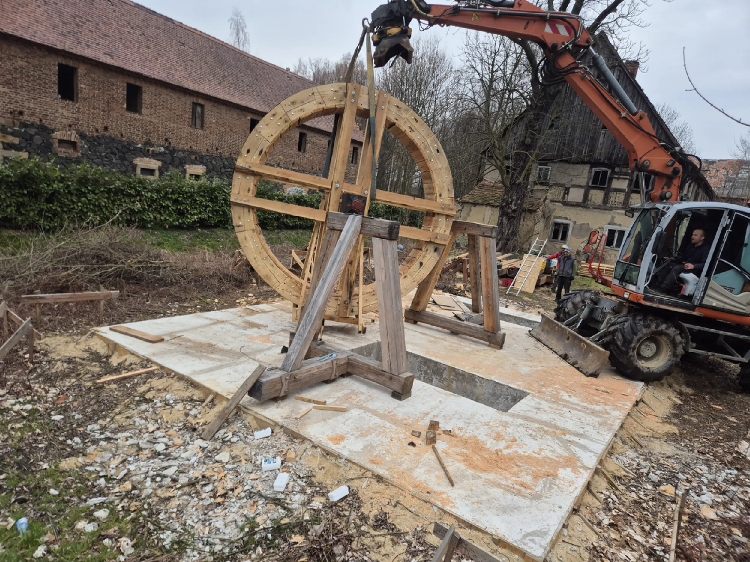
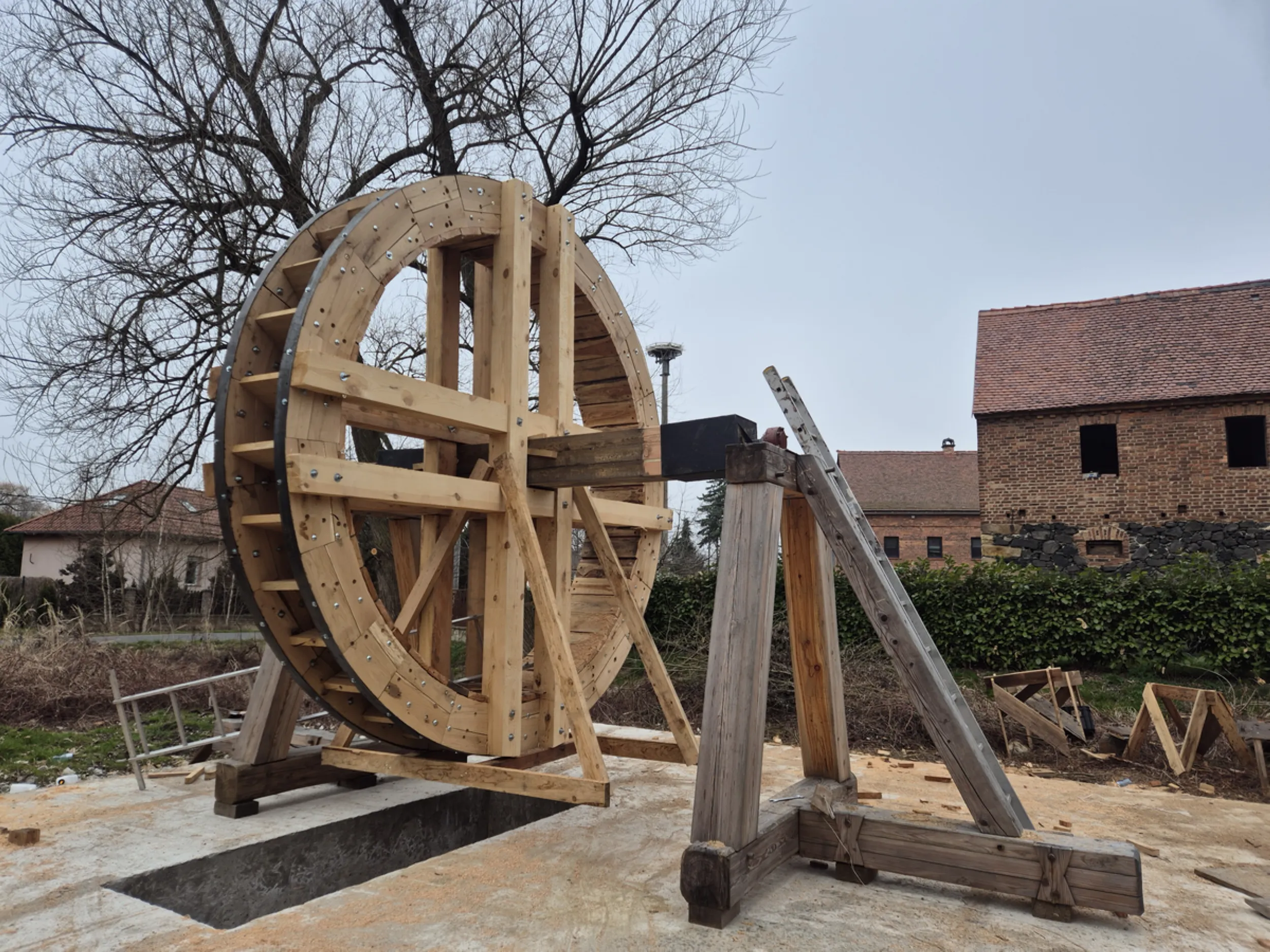
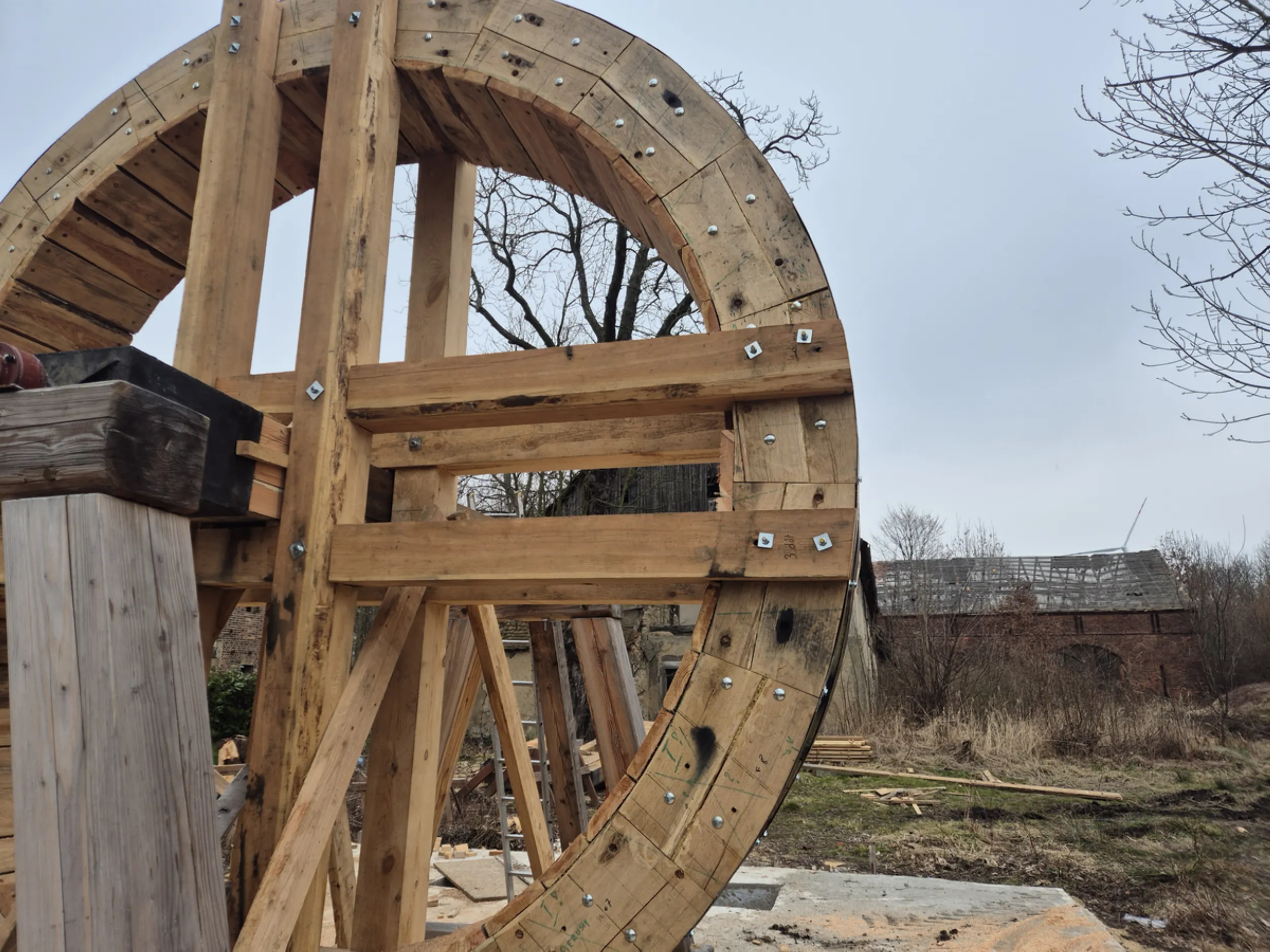
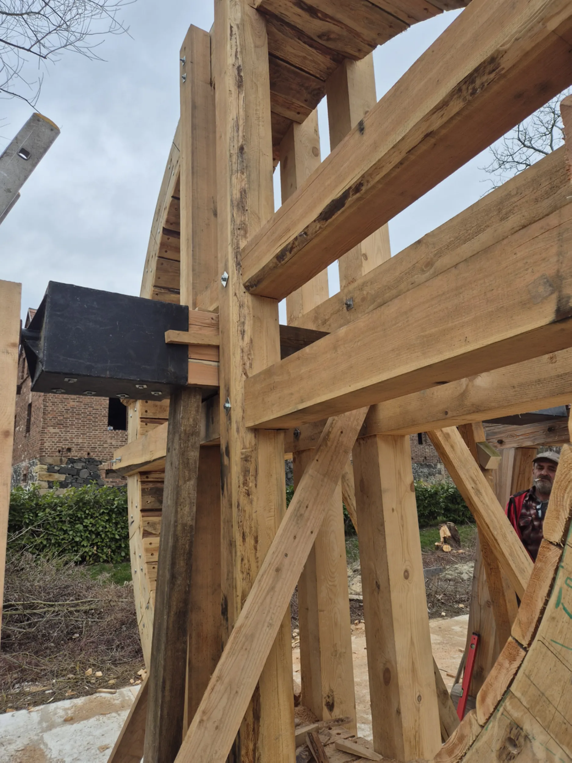
10 – Rurmus Water Wheel
The water wheel is the most important and recognizable element of the entire device. Constructed of wood, its design draws upon techniques used by the builders of historic mills, sawmills, and other machinery powered by flowing water. Visible features include the rims, the spoke arrangement, the central axle, and the components responsible for transmitting the forces generated during the mechanism’s operation.
Assembling the wheel required maintaining precise structural geometry, as even minor deviations could affect its smooth rotation and its interaction with the rest of the device. Due to the structure’s large dimensions and weight, mechanical equipment was required to position and fit the individual components together.
The water wheel is the heart of the Rurmus. It converts the energy of flowing water into the mechanical motion used to drive the entire water lifting and transport system.
- rurmus project -
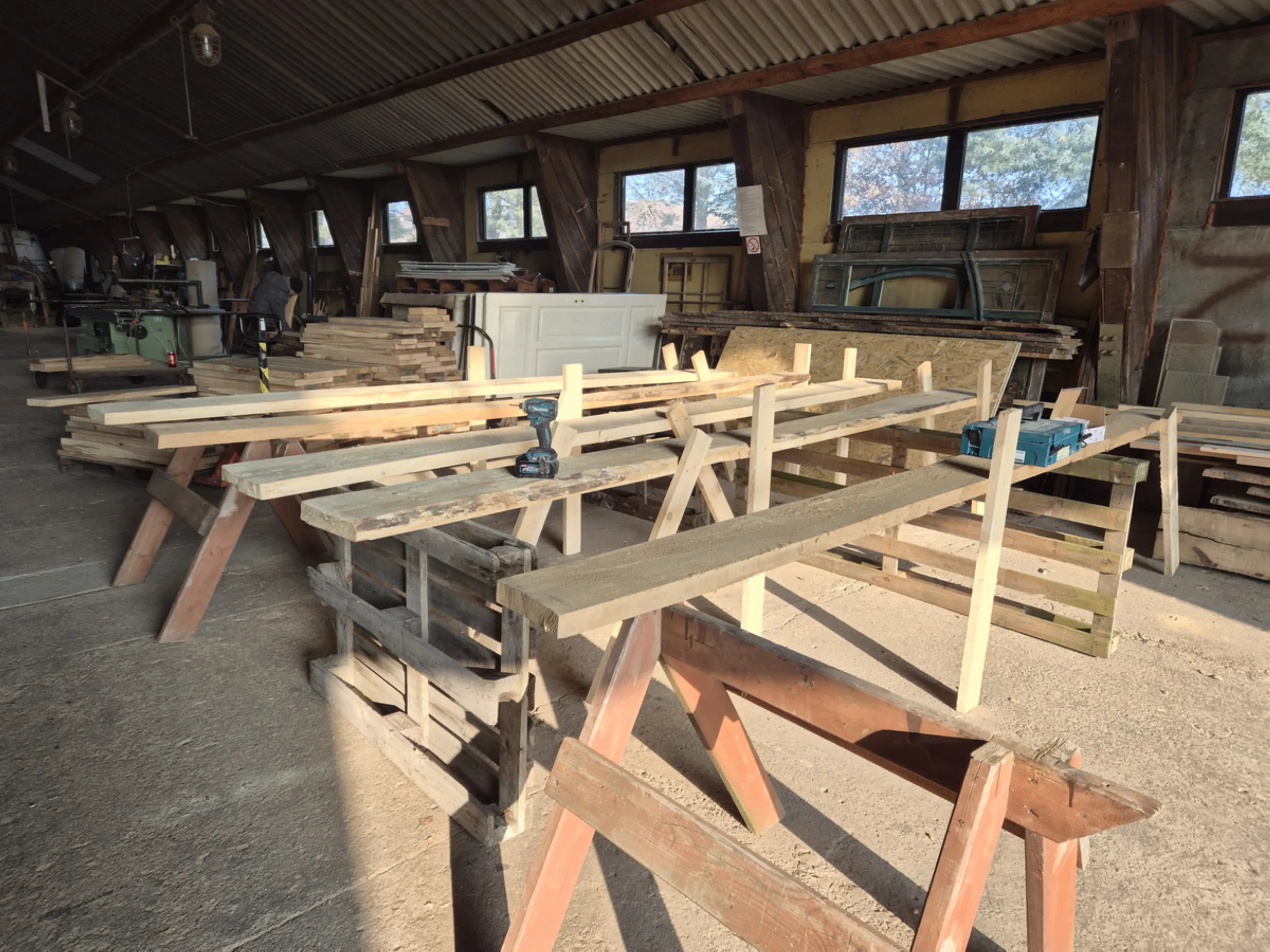
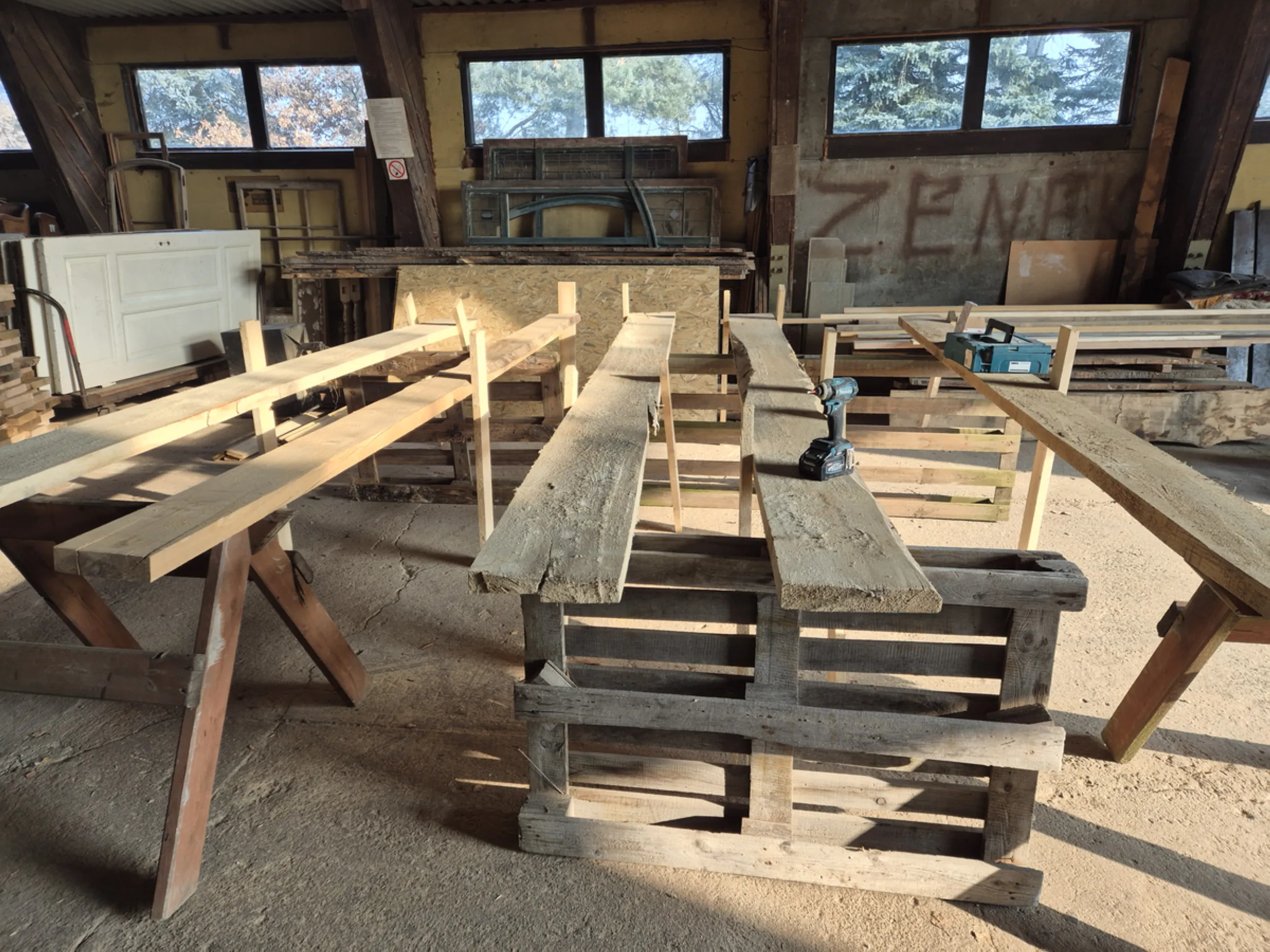
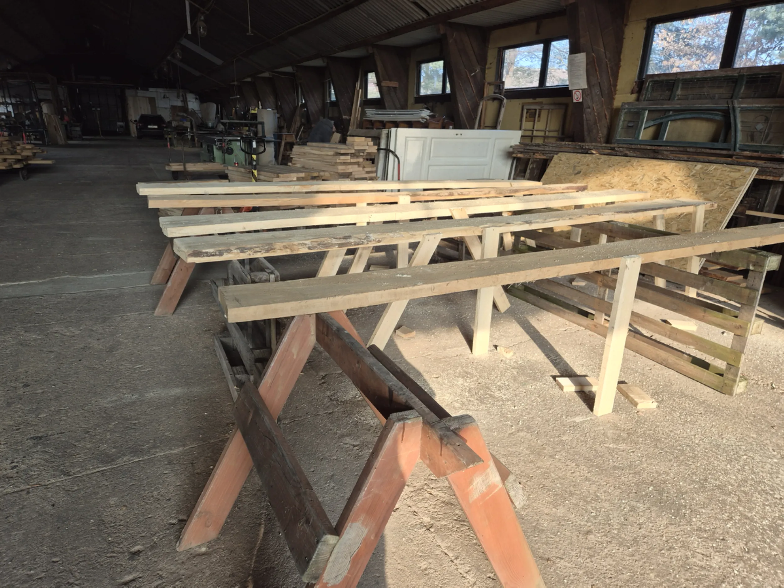
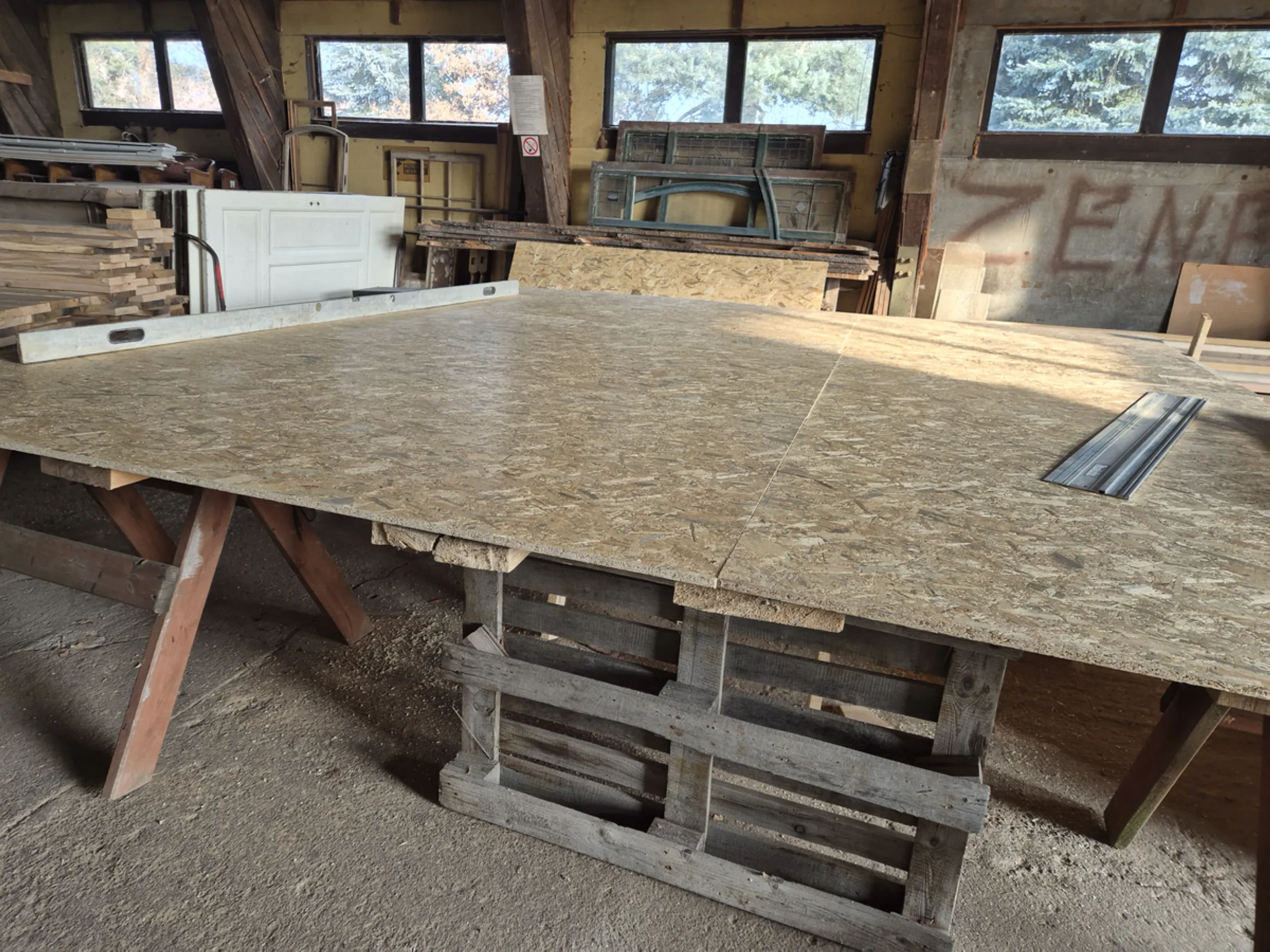
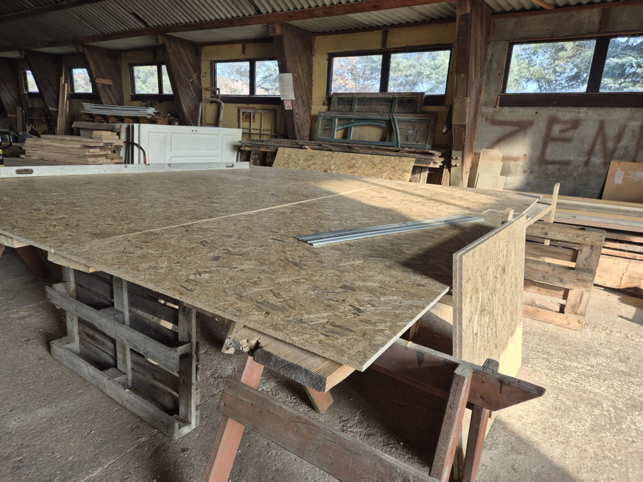
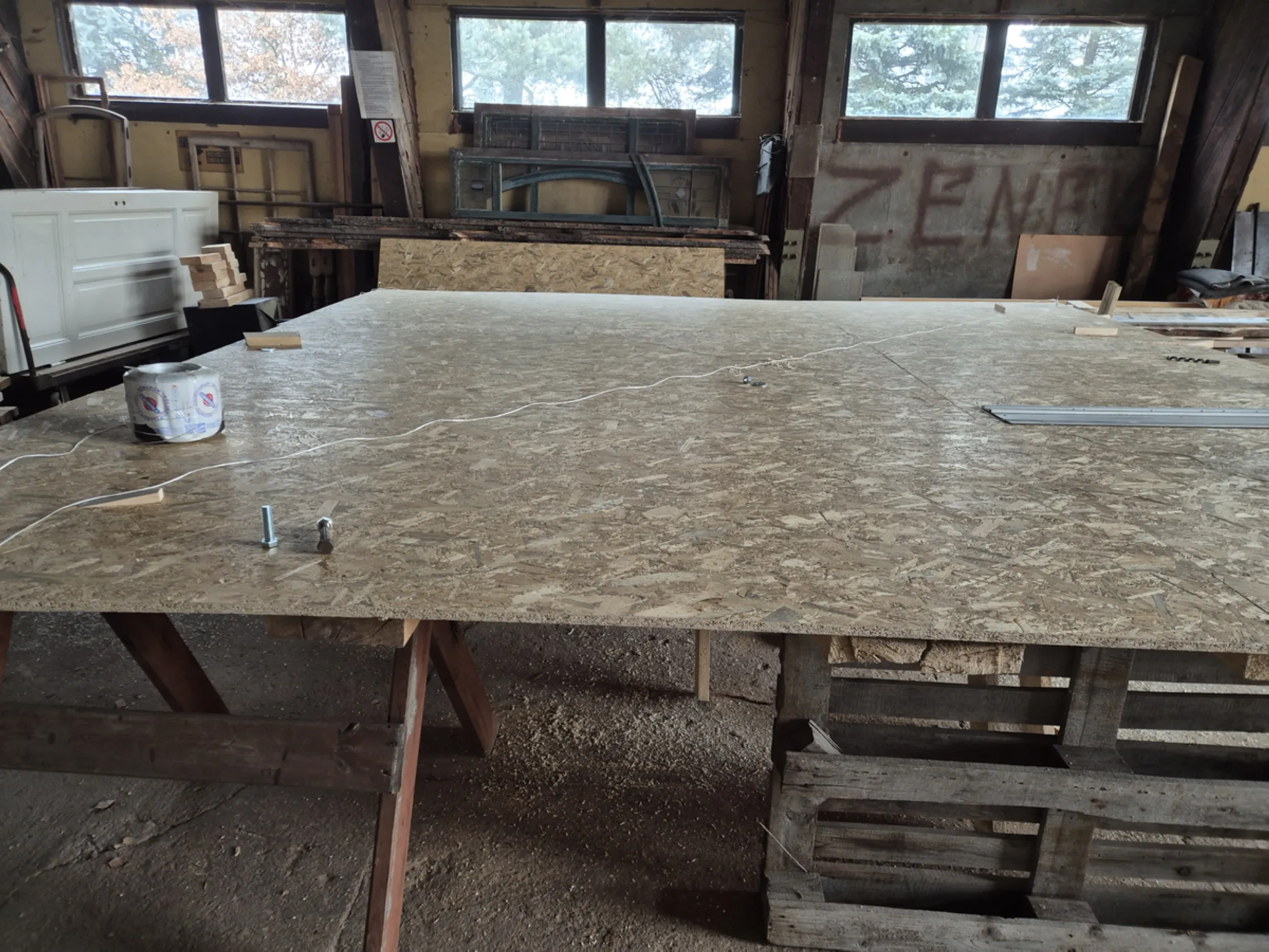
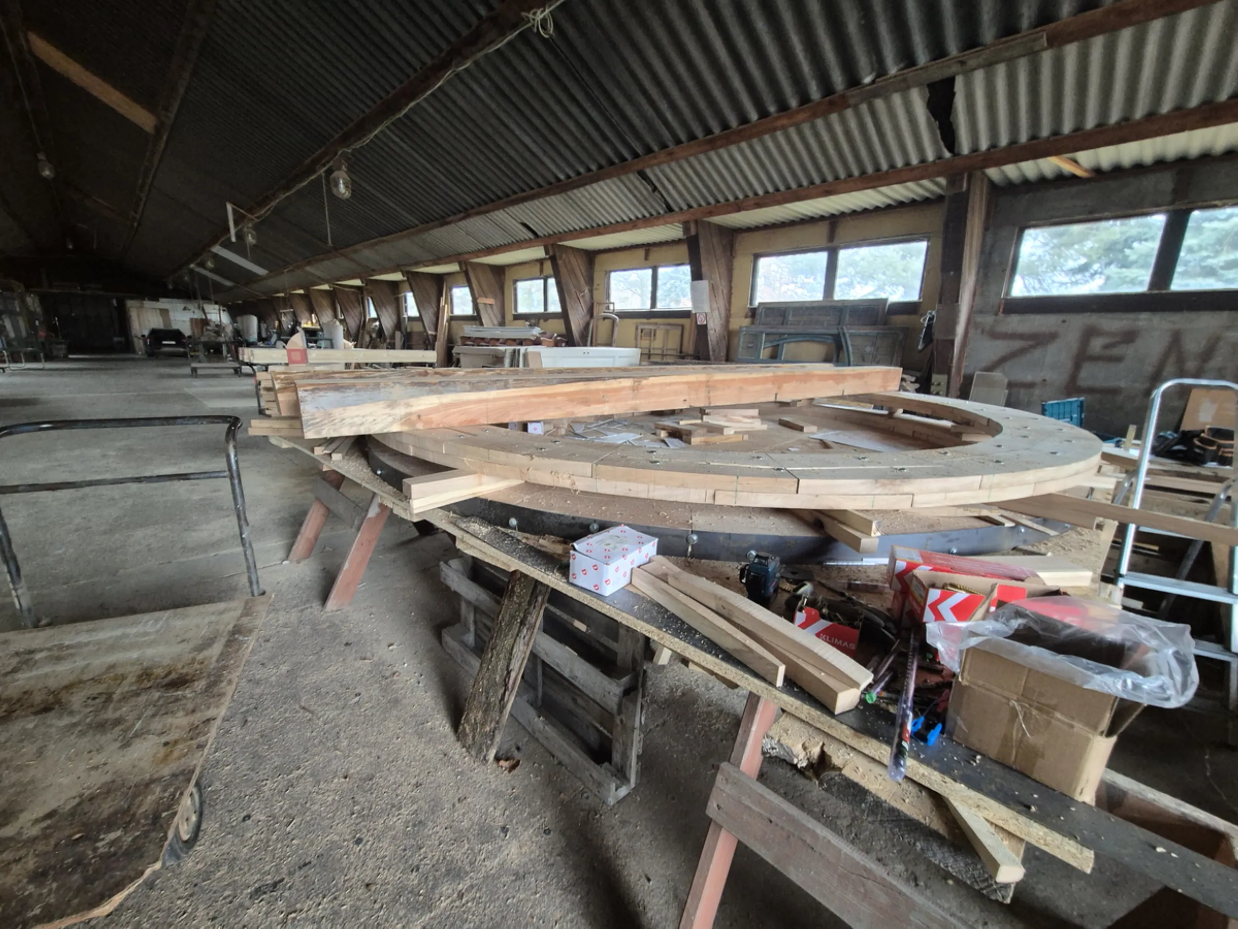
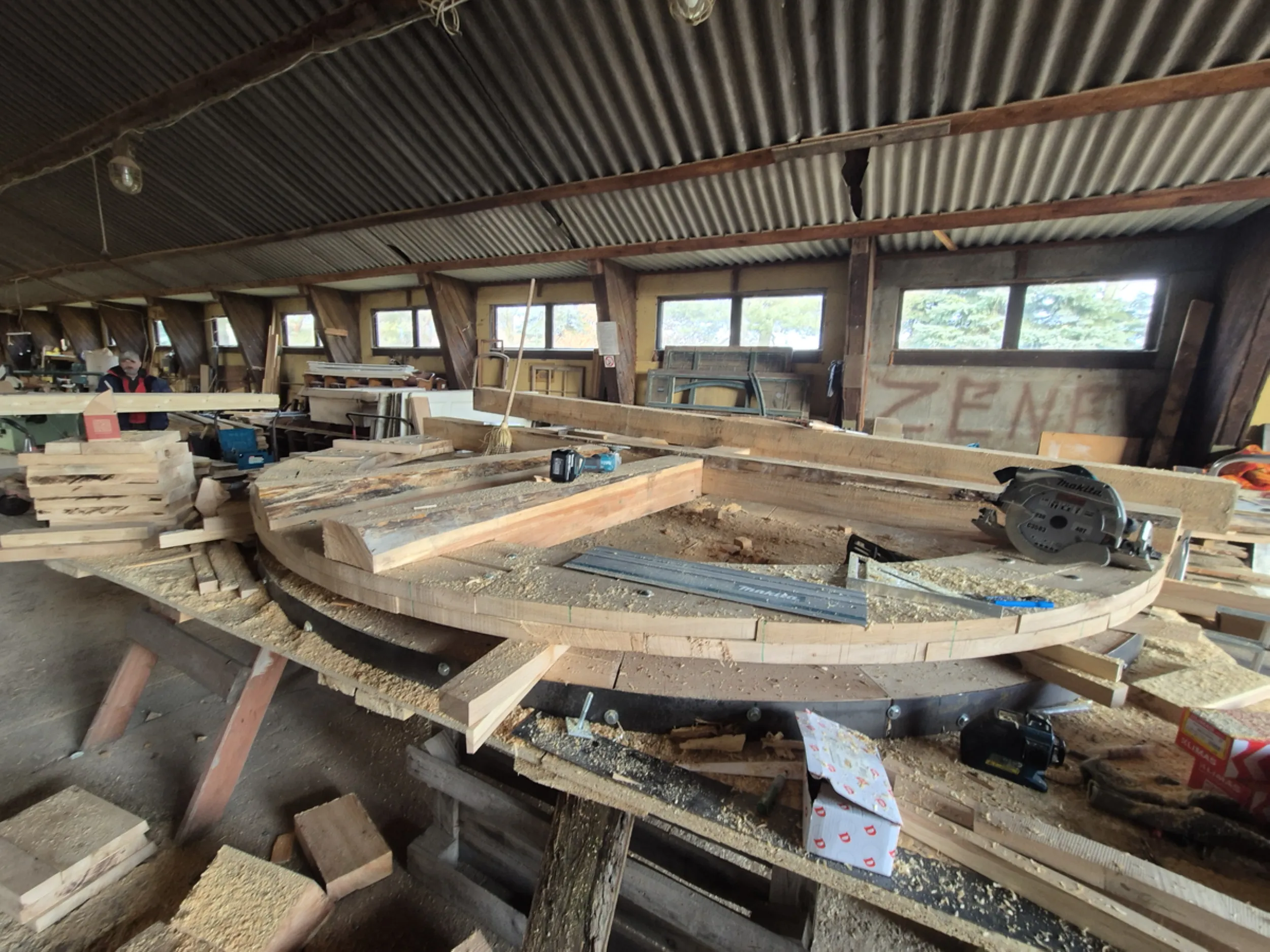
11 – Preparing the waterwheel construction workspace
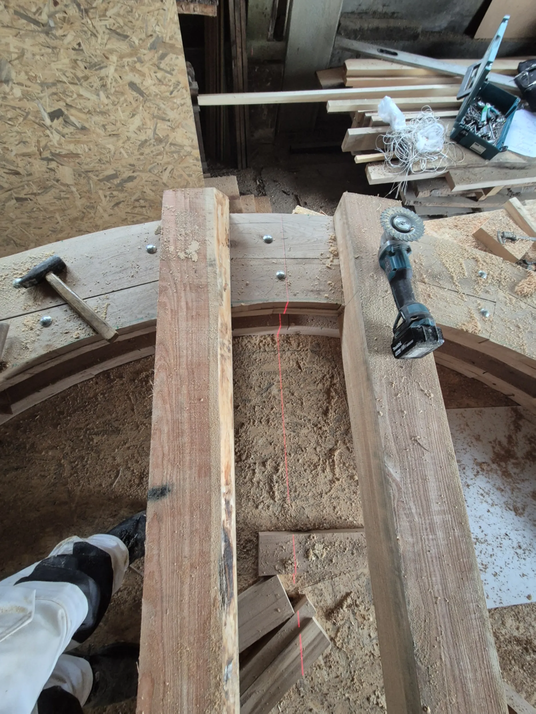
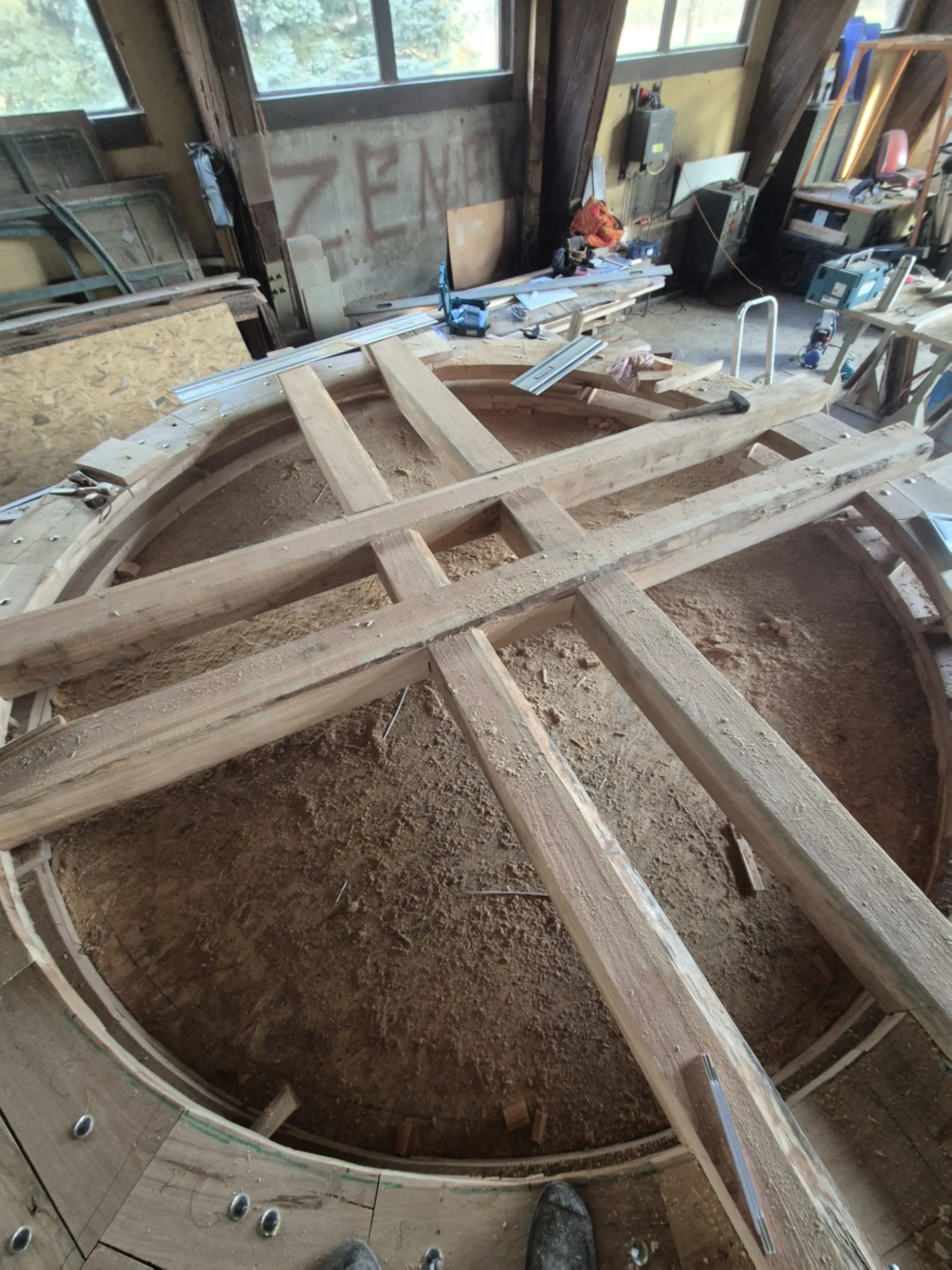
Building the waterwheel required setting up a dedicated workspace that allowed for precise layout, measurement, and assembly of large-scale components. To this end, an assembly table was prepared that also served as a control template for the individual structural parts.
A significant portion of the work was devoted to establishing the wheel’s axis, marking out division points, and preparing templates for subsequent woodworking. It was at this stage that the geometry of the entire structure was determined—a factor crucial for the later fit of the rim, spokes, and other load-bearing elements.
The prepared workspace enabled repeated dimensional checks and ensured consistency in the parts being produced. It served as the foundation for constructing one of the largest wooden components of the entire *Rurmus*.
- rurmus project -
12 – The Birth of the Water Wheel Structure
This stage marks the moment when individual wooden components began to form the actual structure of the water wheel. The main spokes and the central elements defining the future axis of rotation were laid out at a pre-prepared assembly station. Assembly of the first disc—which would serve as the foundation for the entire wheel—then began.
Maintaining uniform angular spacing, precisely locating the center, and carefully checking the relative positioning of all parts were of critical importance. Even slight deviations could later affect the smoothness of rotation and the proper functioning of the entire mechanism.
It was at this stage that the theory embodied in the drawings and templates began to take tangible form. The emerging disc became the framework for one of the largest and most distinctive components of the *Rurmus*.
- rurmus project -
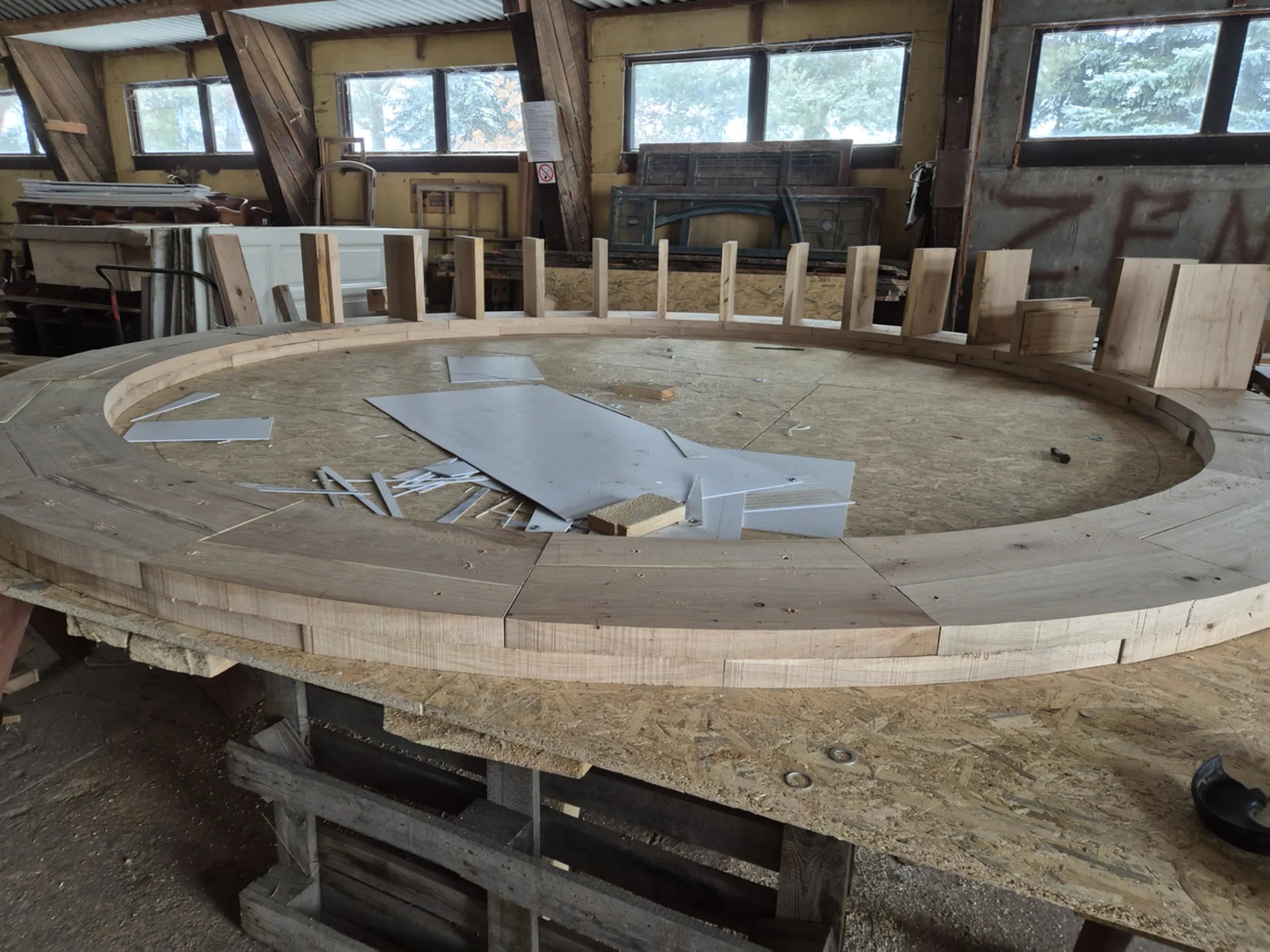
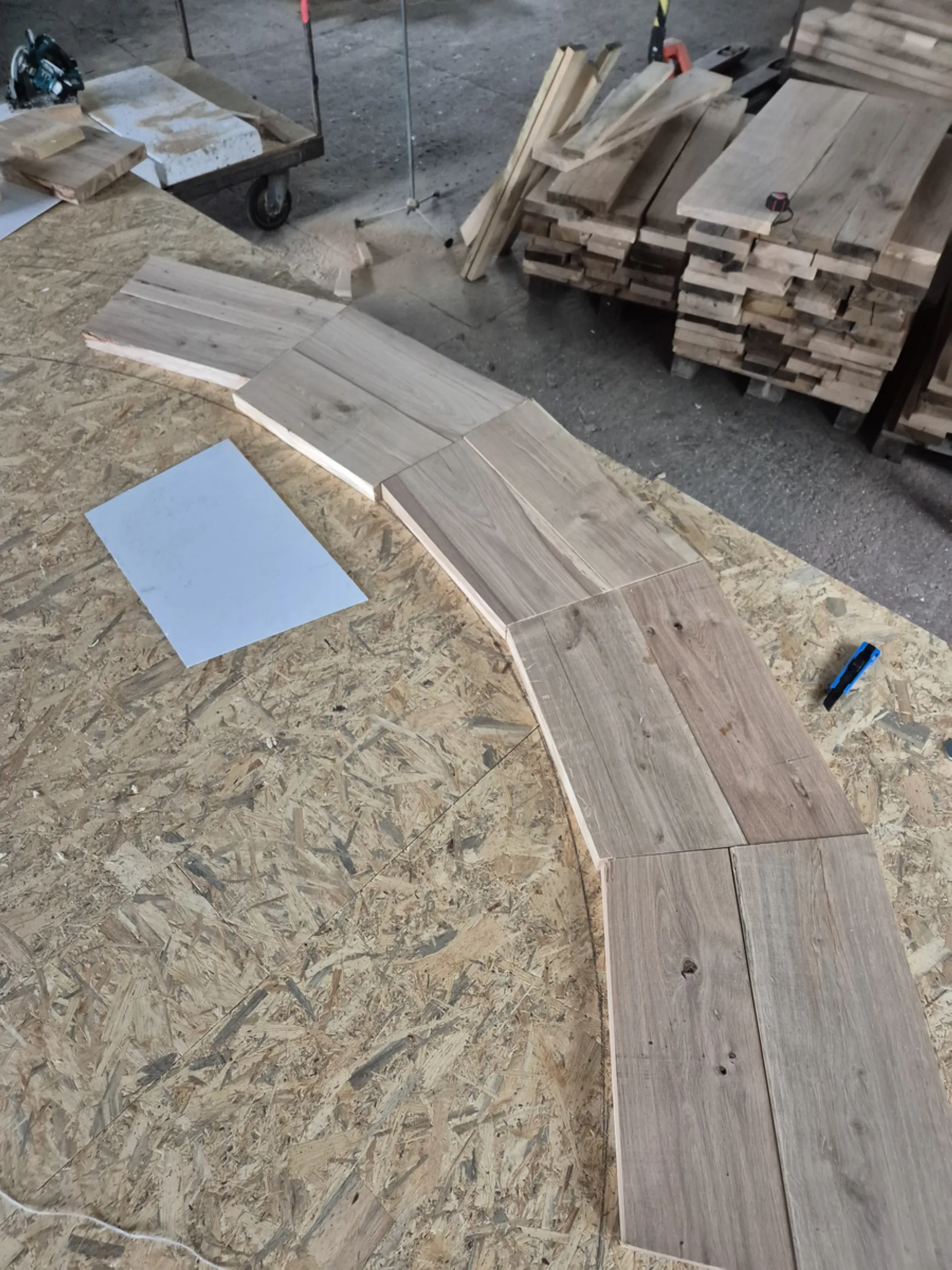
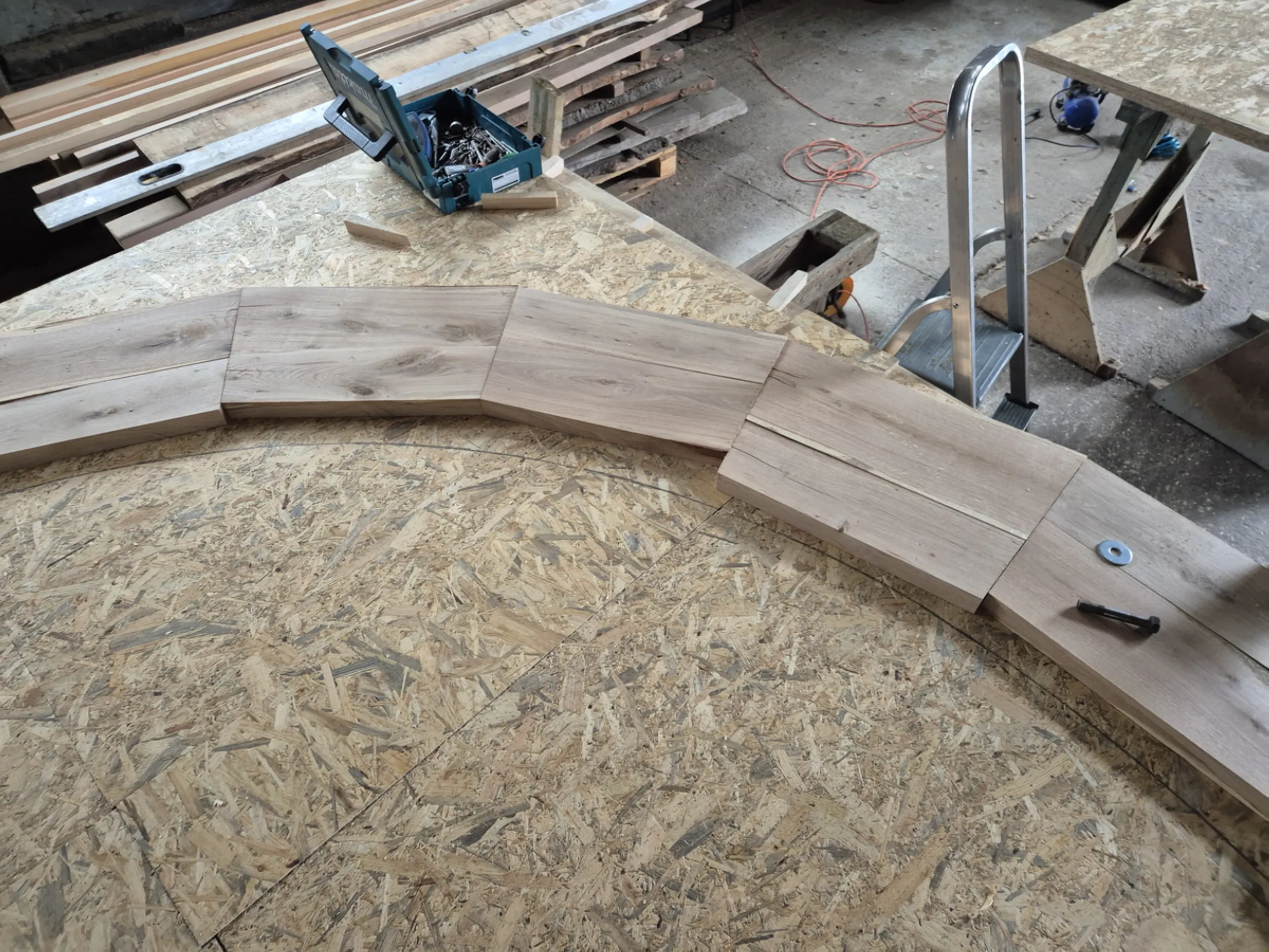
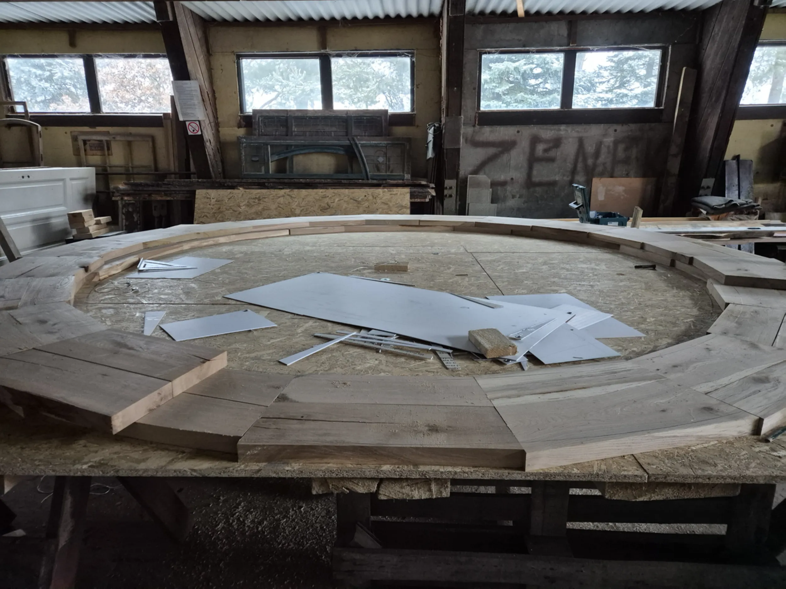
13 – Constructing the Water Wheel Rims and Buckets
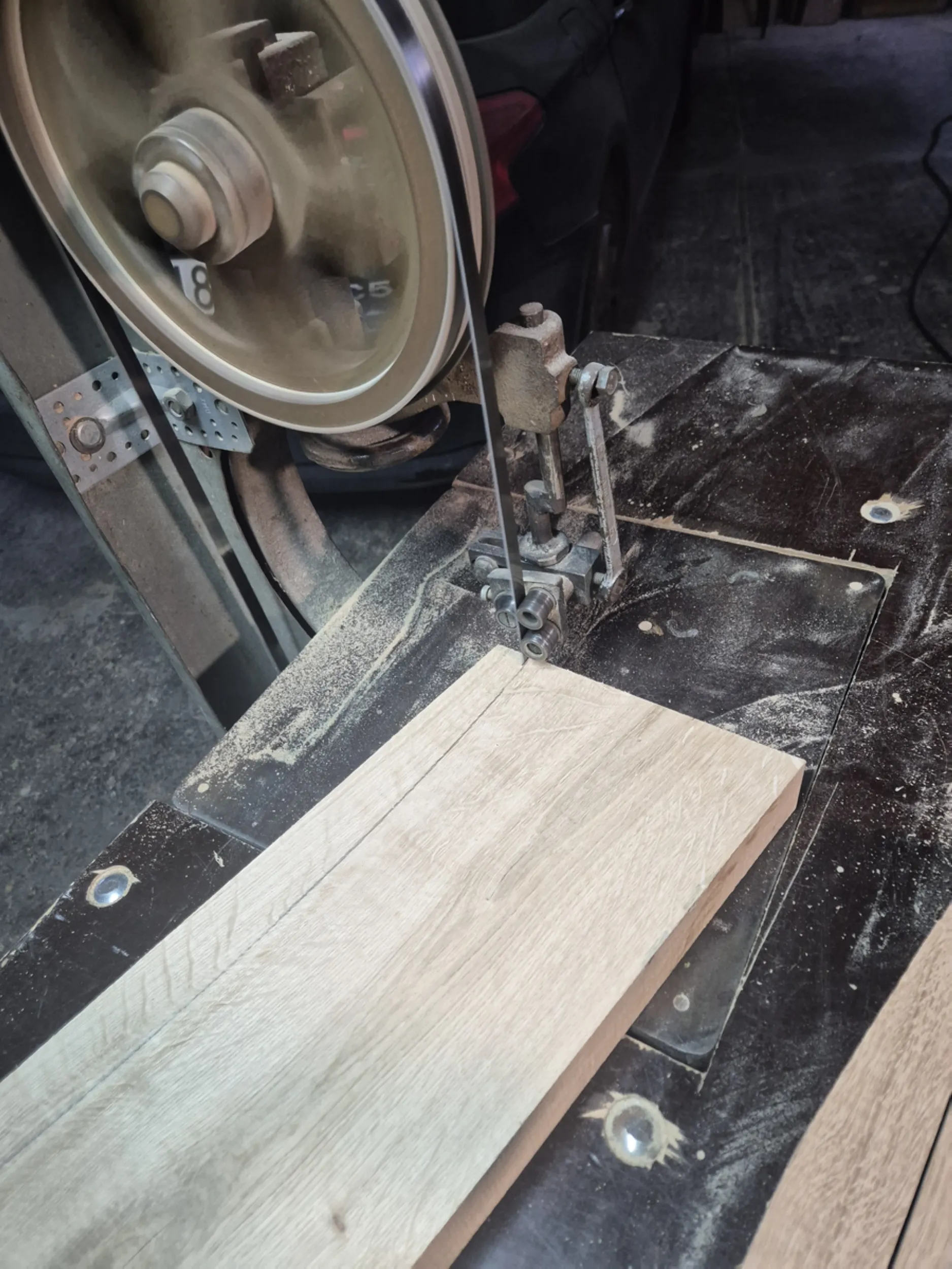
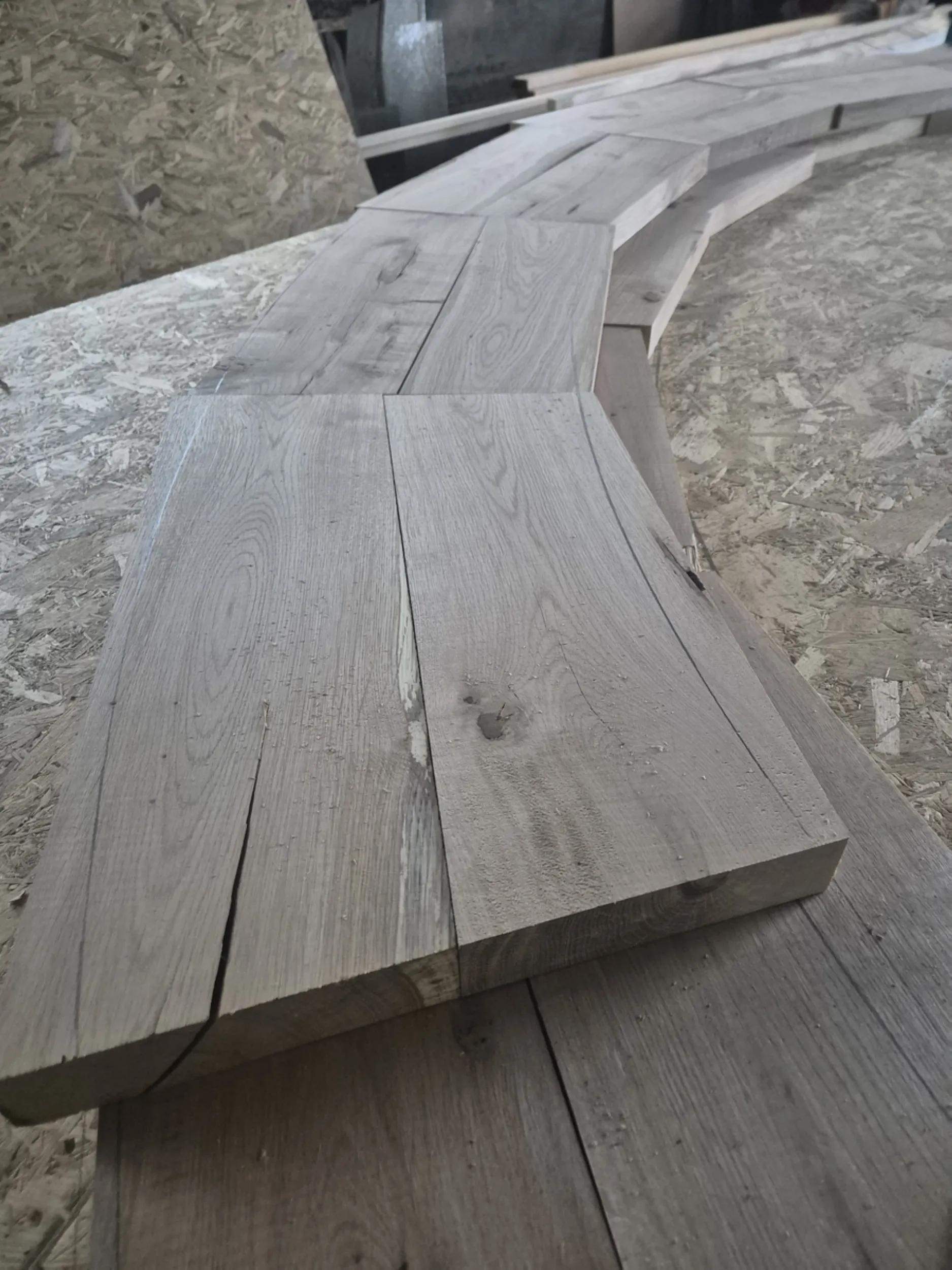
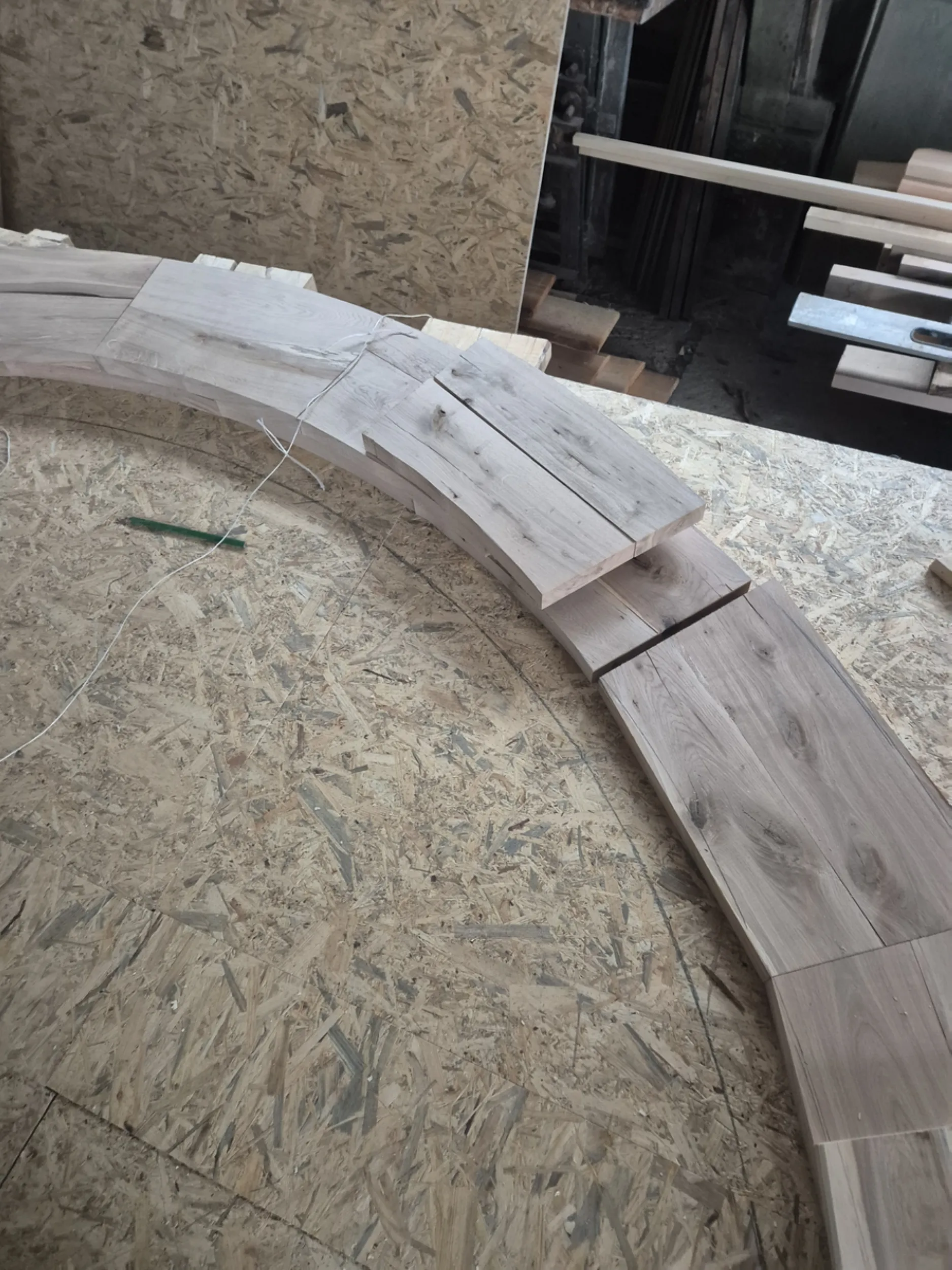
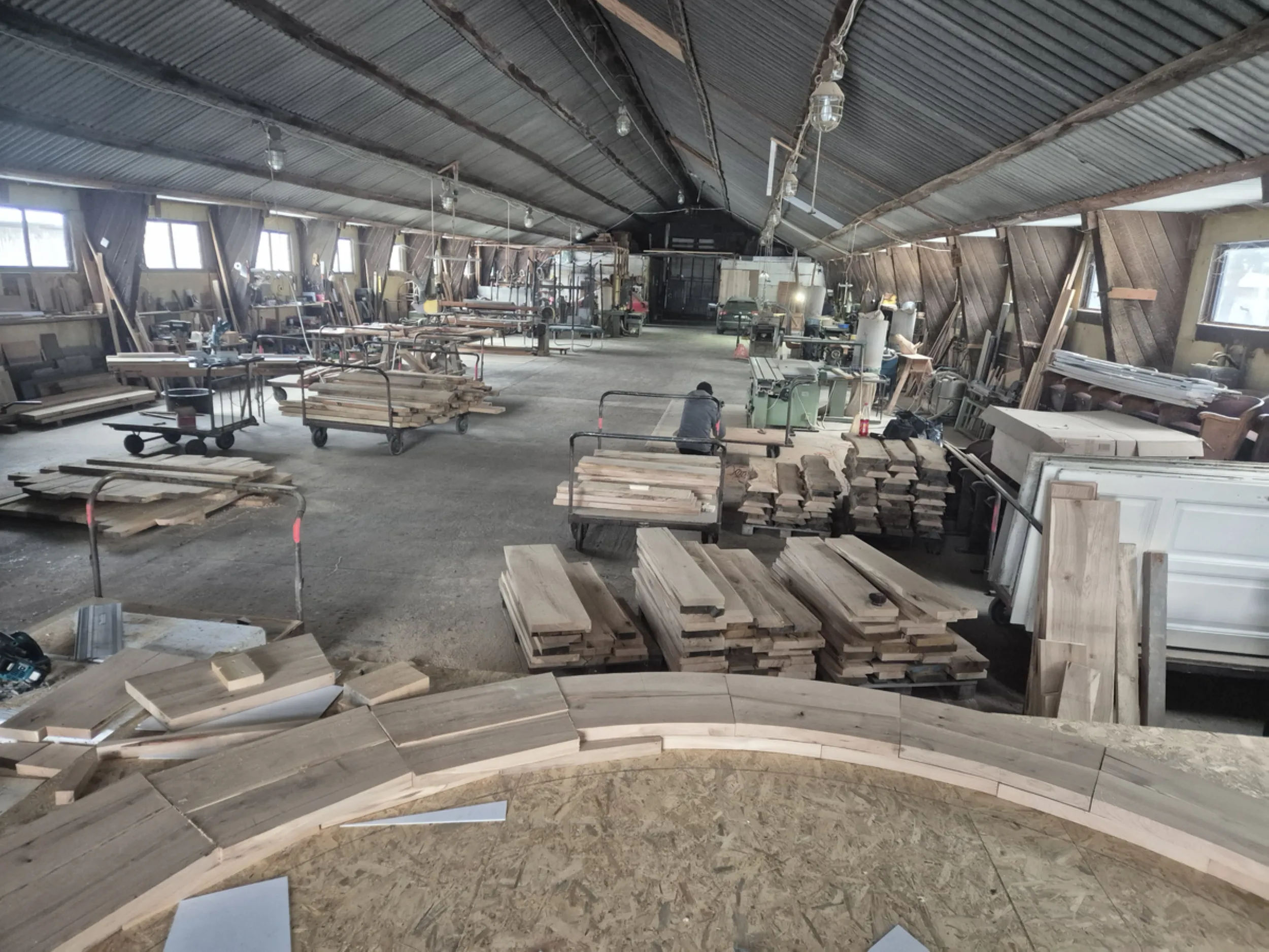
Work focused on preparing the components that form the outer part of the water wheel. Rim segments were crafted from precisely shaped timber; once joined, they would form the complete structural ring. Each element required maintaining the correct radius and ensuring a precise fit in accordance with the wheel’s pre-determined geometry.
Simultaneously, the partitions forming the characteristic buckets—responsible for capturing and transporting water—were being prepared. These components are crucial for the wheel’s operational efficiency and the effective utilization of the flowing water’s energy.
This stage marks the transition from a skeletal framework to a form that begins to resemble the finished water wheel. The emerging rims and buckets give the structure its final character and prepare it for the subsequent assembly stages.
- rurmus project -
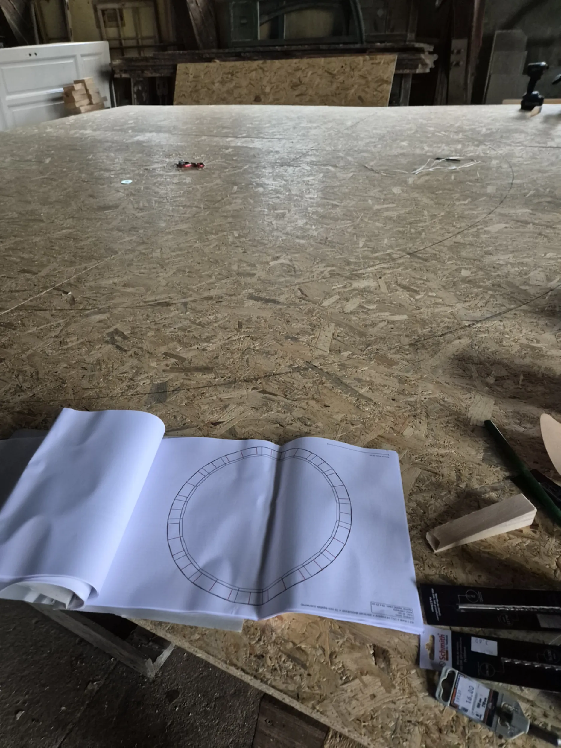
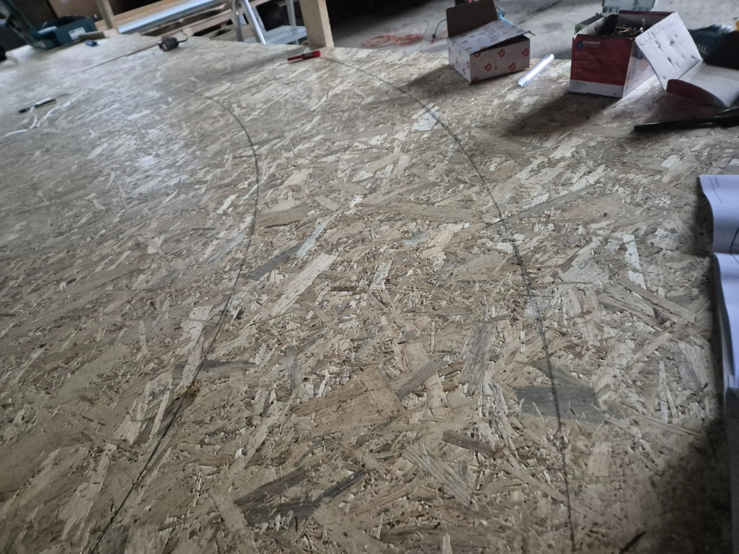
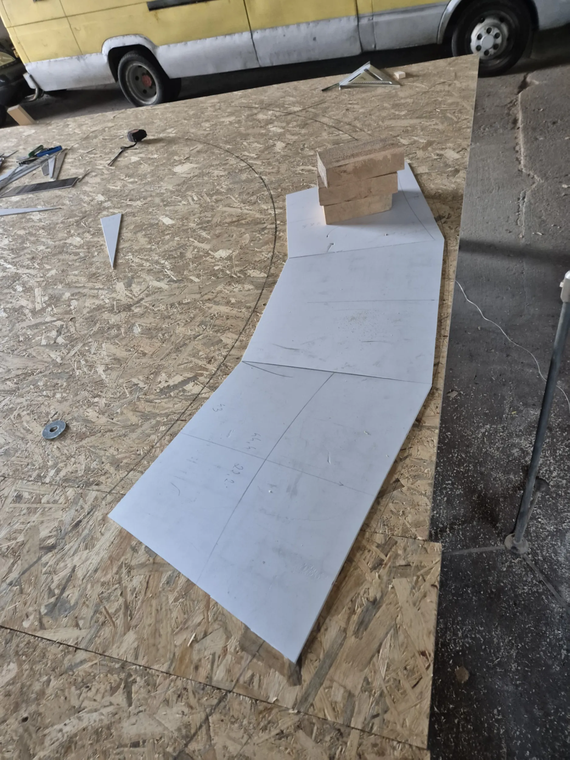
14 – Full-scale water wheel geometry
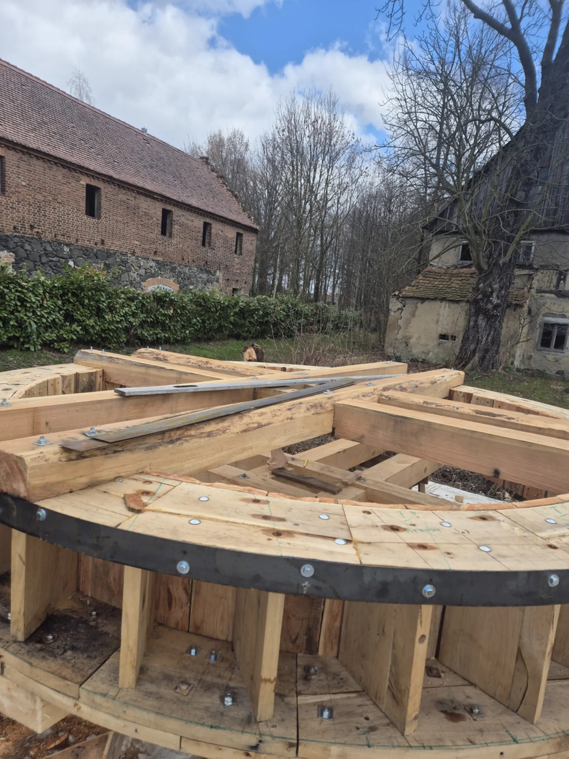
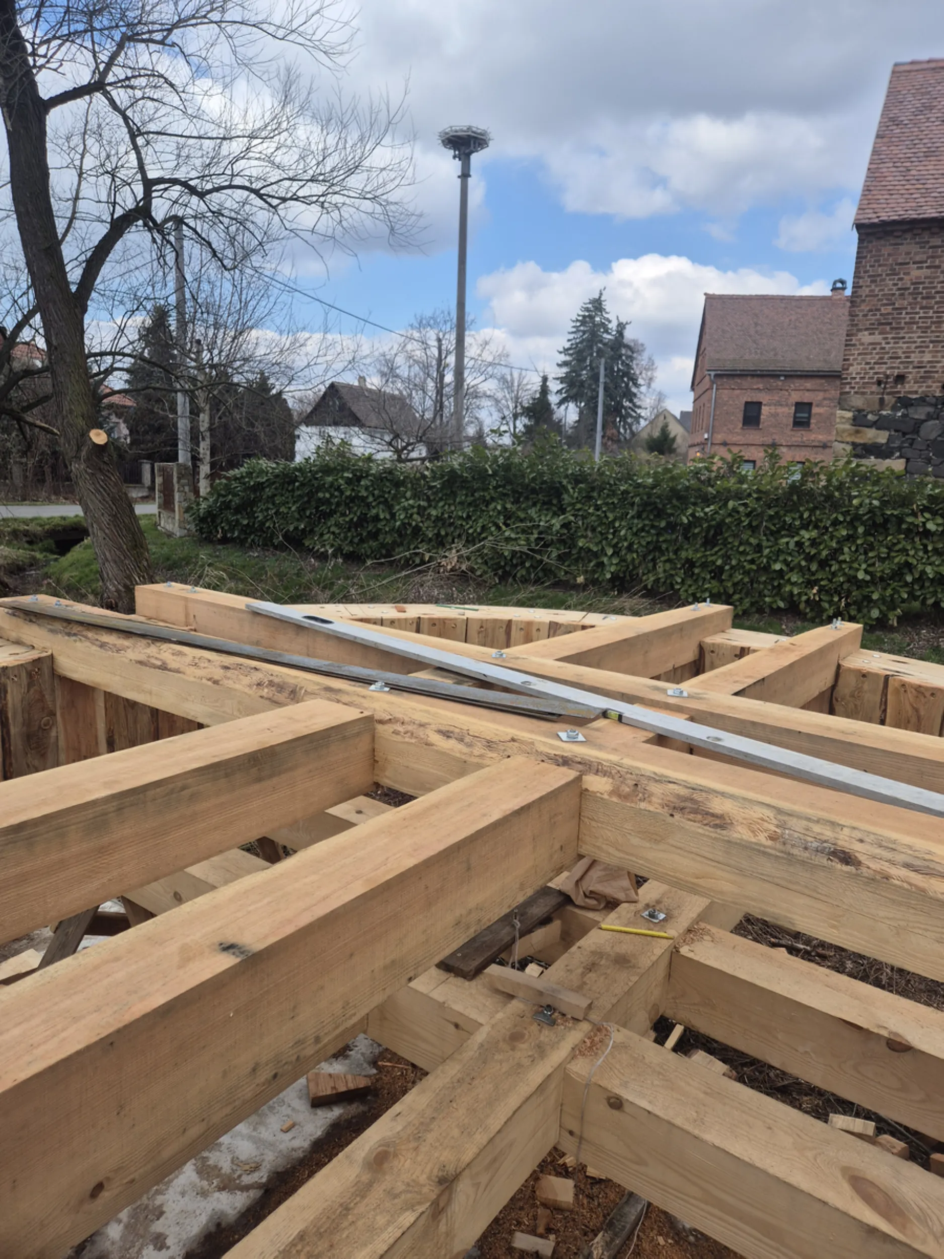
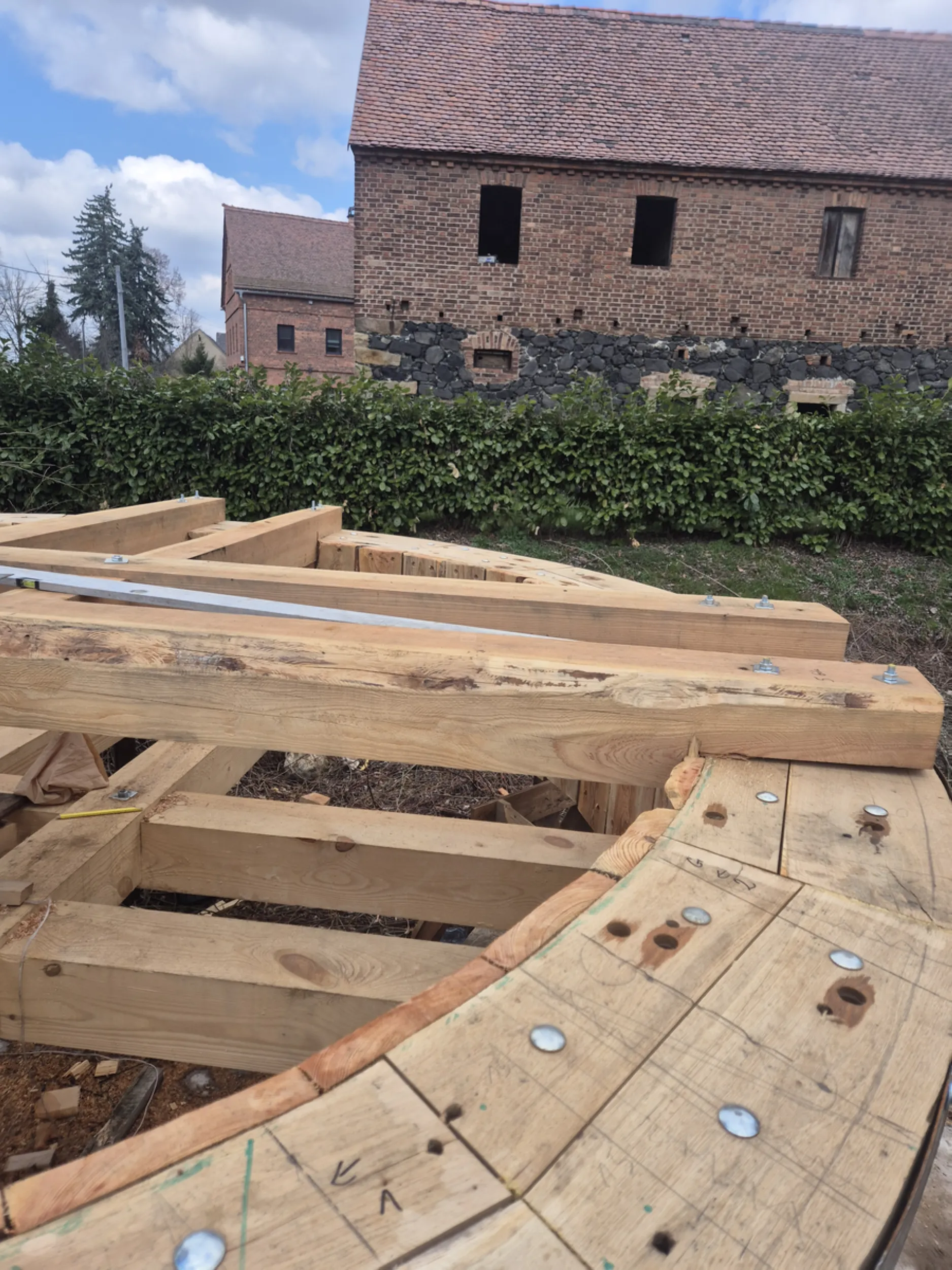
When constructing large wooden structures, technical documentation alone is often insufficient. Therefore, the full outline of the water wheel was laid out at actual size directly on the workshop floor. This allowed for the precise determination of the diameter, axis of rotation, spoke positions, and the layout of all structural components.
The resulting workshop drawing served as a template for the subsequent processing and assembly of the individual parts. It enabled continuous monitoring of the wheel’s geometry and ensured consistency across the manufactured components.
This is one of those stages that is rarely visible in the finished structure, yet it largely determines the structure’s precision, proportions, and proper functioning.
- rurmus project -
15 – Assembling the Water Wheel
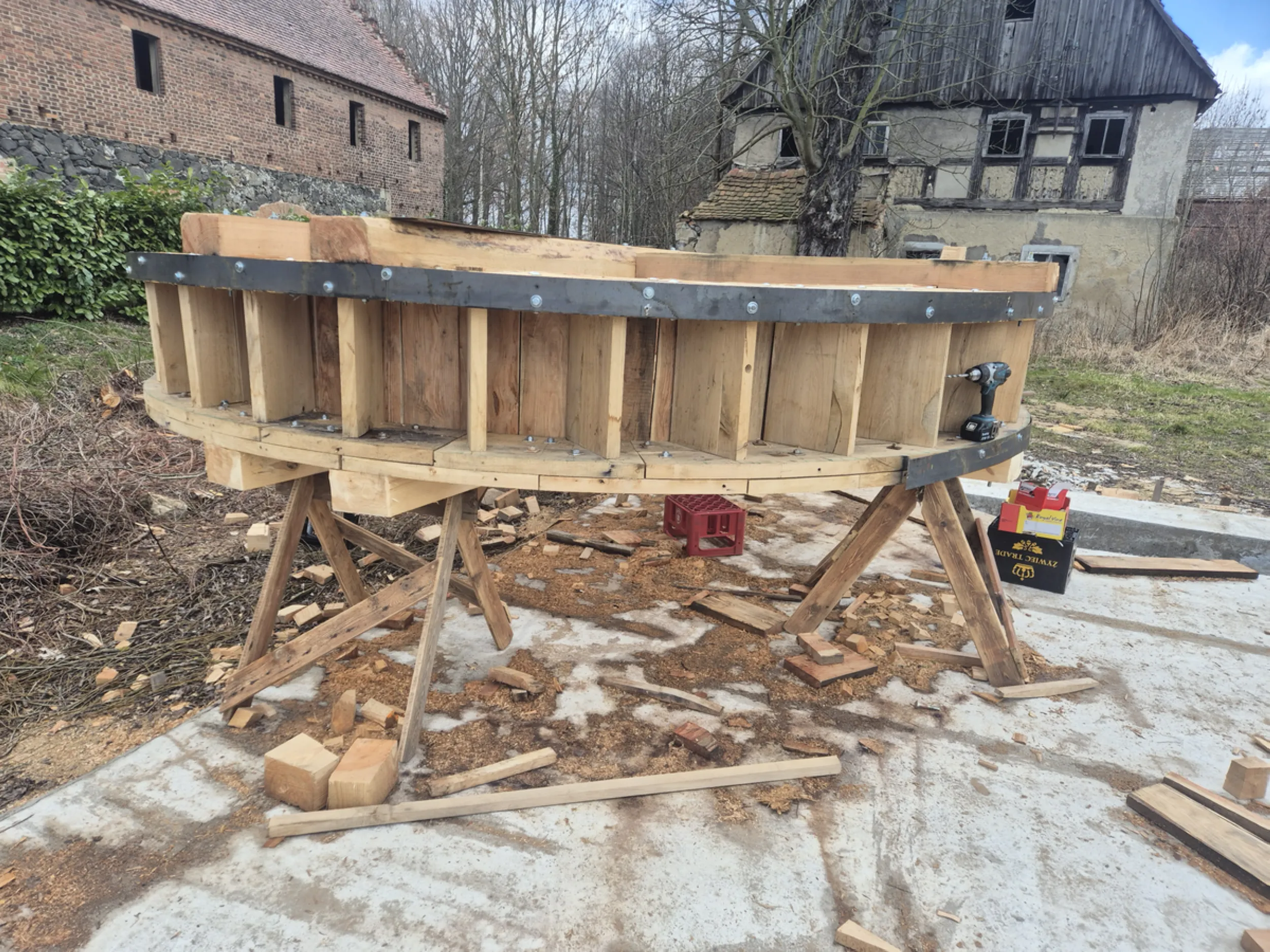
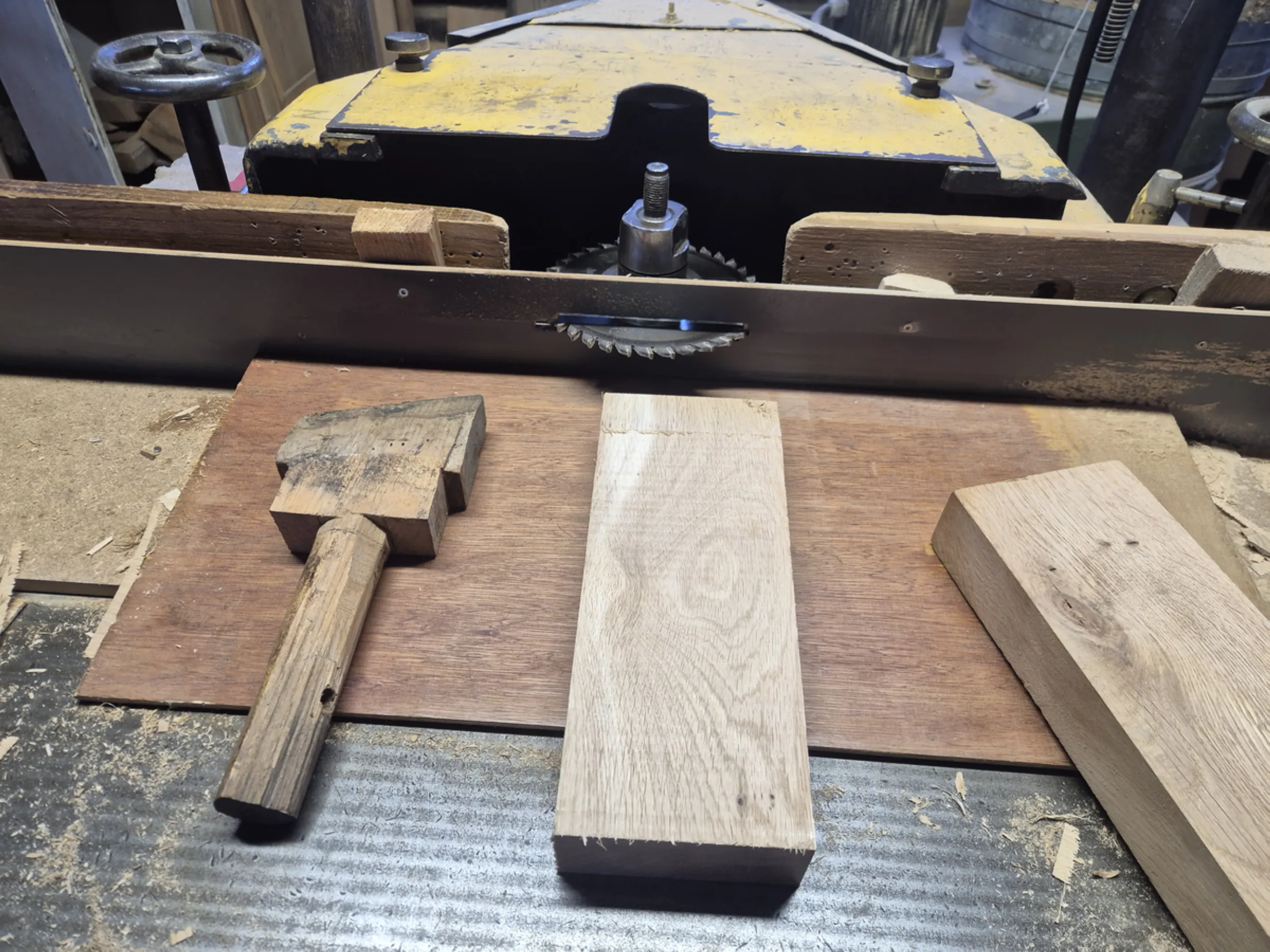
At this stage, the individual parts began to form the complete water wheel structure. The rims, spokes, and working elements were joined into a unified assembly designed not only to bear loads but also to effectively harness the energy of the flowing water.
Precision in the placement of the buckets and maintaining the balance of the entire structure were of particular importance. Each component had to be positioned correctly to ensure the wheel operated smoothly, without placing excessive strain on the axle and bearing system.
The work shown here captures the moment when weeks of machining individual parts transform into a full-scale water wheel. This is one of the most spectacular stages of the Rurmus construction, as the structure takes on its final form and begins to resemble the completed device.
- rurmus project -
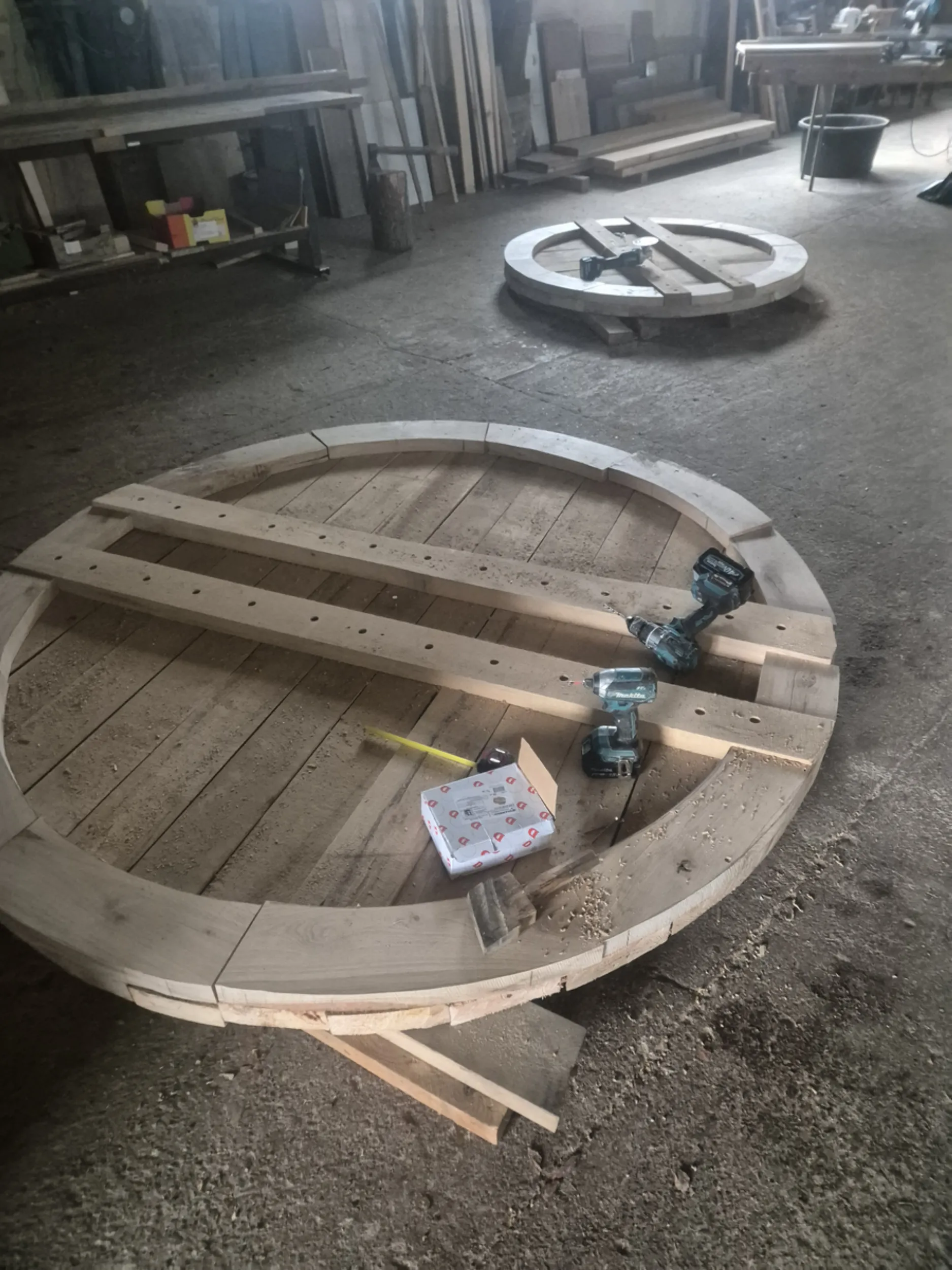
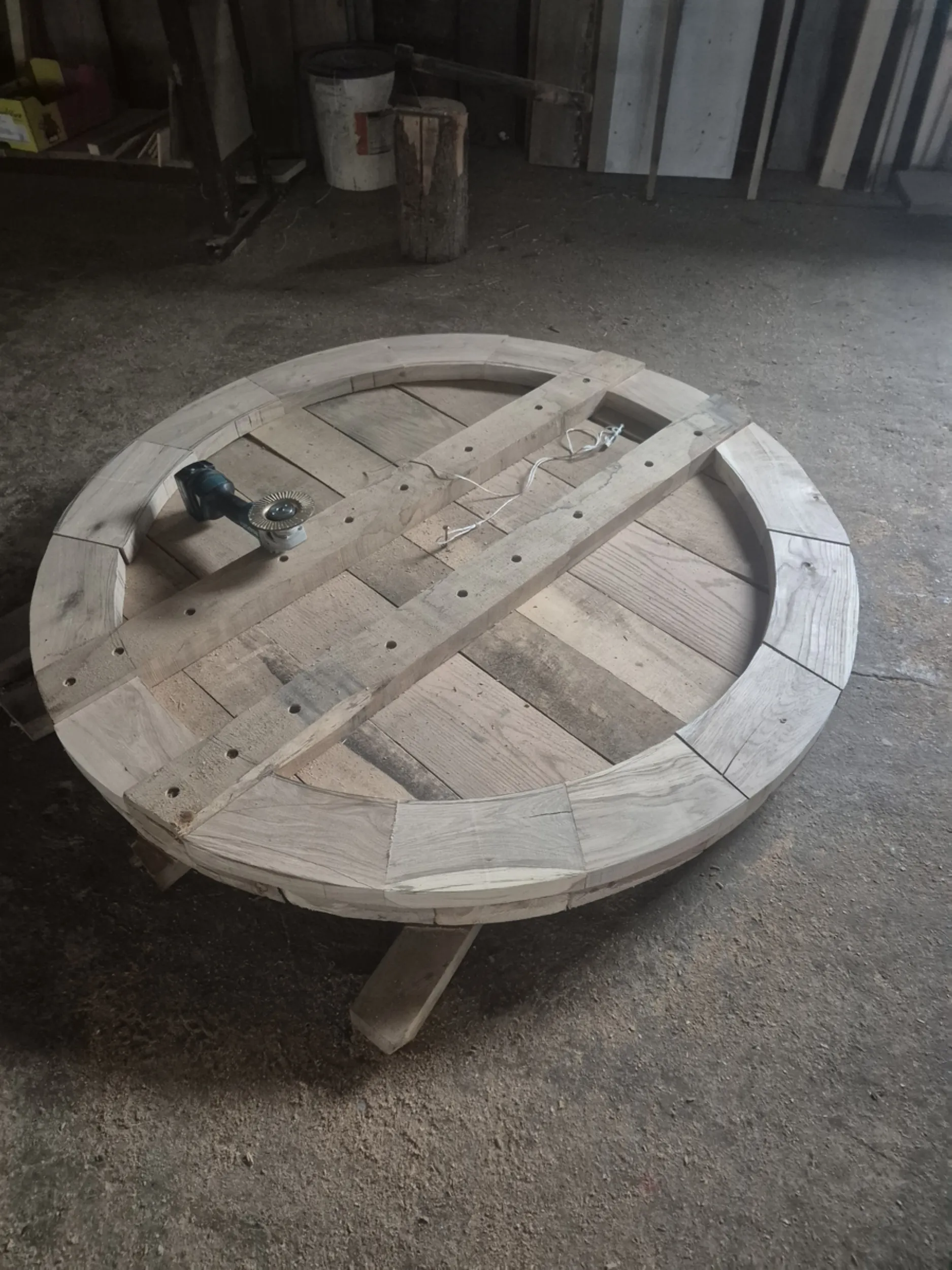
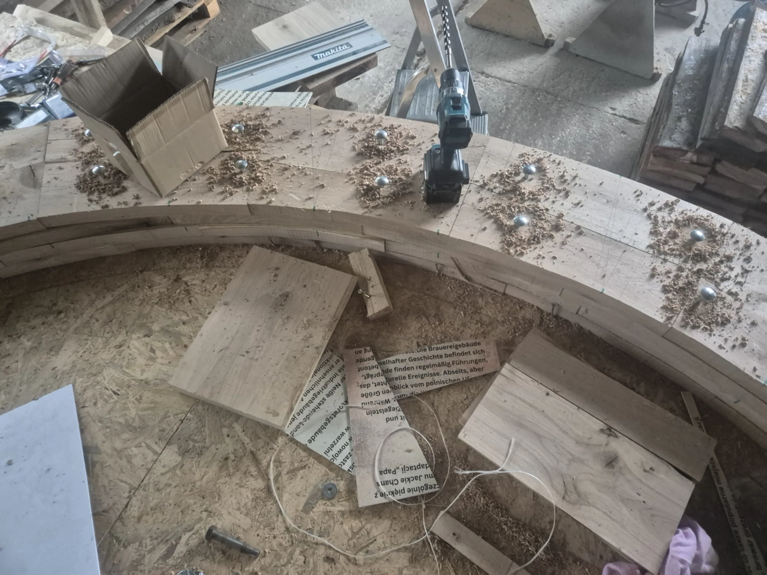
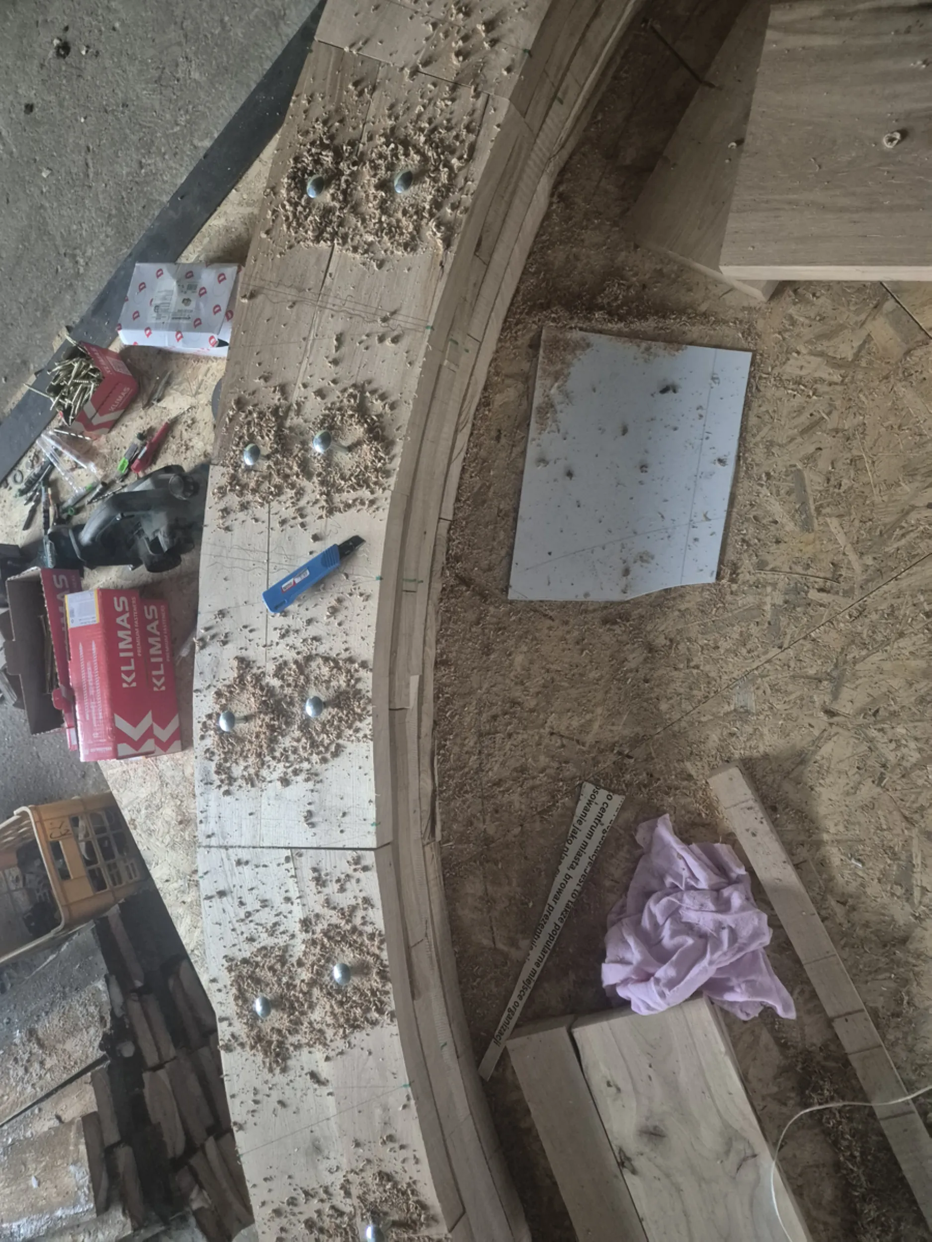
16 – Wooden Gear Teeth
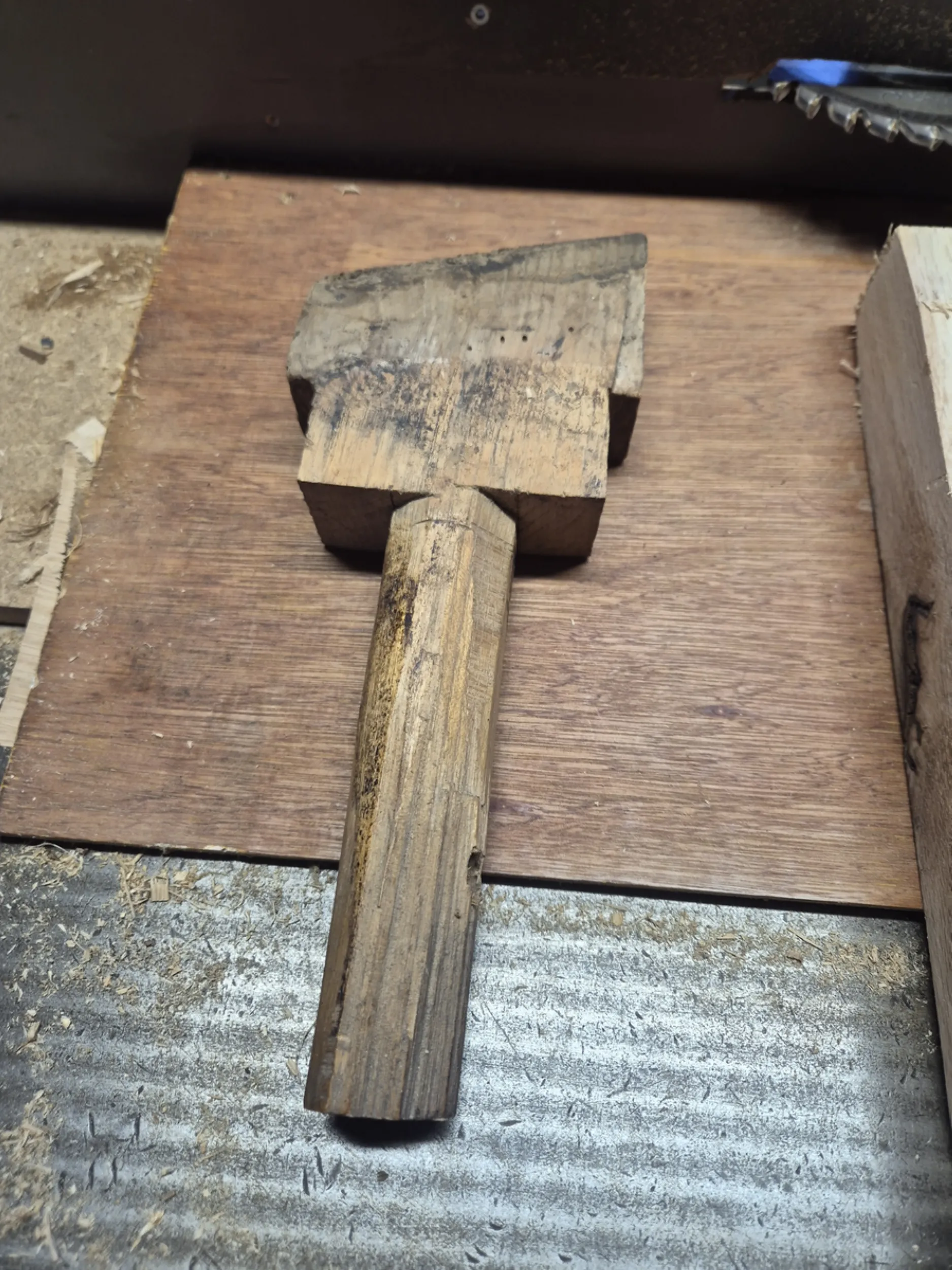
One of the most distinctive features of the Rurmus mechanism is the set of wooden teeth that mesh with the gear wheels. Crafting them required maintaining a uniform shape, dimensions, and mounting angle, as even slight variations could affect the smooth operation of the entire drive system.
Production was based on a master component known to the carpenters as the “mother tooth.” This piece defined the geometry of all subsequent parts and ensured complete consistency in their manufacture. Each tooth was individually shaped, inspected, and fitted before being installed in the gear wheel.
The work shown here illustrates technical solutions—rarely seen today—that were once commonly used in mills, sawmills, and water-powered machinery. Instead of metal gears, wood was used; when properly crafted, it ensured the mechanism’s durable and efficient operation for many years.
- rurmus project -
17 – Wooden Gears for the Rurmus Mechanism
The Rurmus mechanism relies on large wooden gears designed to transmit drive between the device’s various components. The work involved preparing the gear rims, constructing segmental joints, and fitting the elements that form their structural framework.
Particular care was required to ensure precise circumferential spacing and the accurate positioning of the slots for the wooden teeth. The subsequent interaction of the gear components and the even transmission of forces during operation depended on this precision.
These gears exemplify traditional technical solutions found in historic mills and water-powered machinery. Their large size, complex geometry, and the need for high manufacturing precision make them some of the most demanding components of the entire Rurmus mechanism.
- rurmus project -
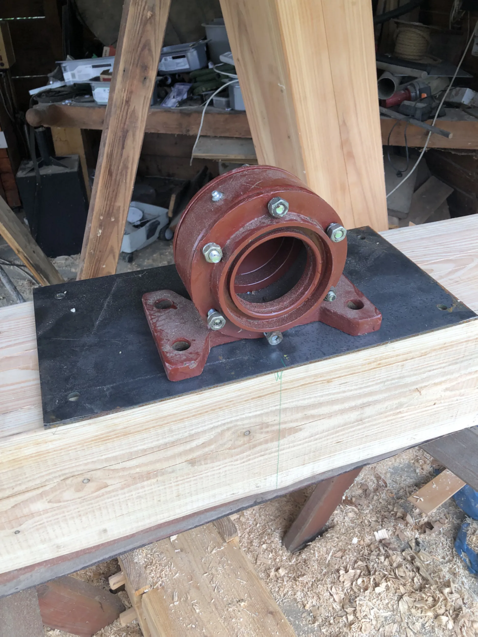
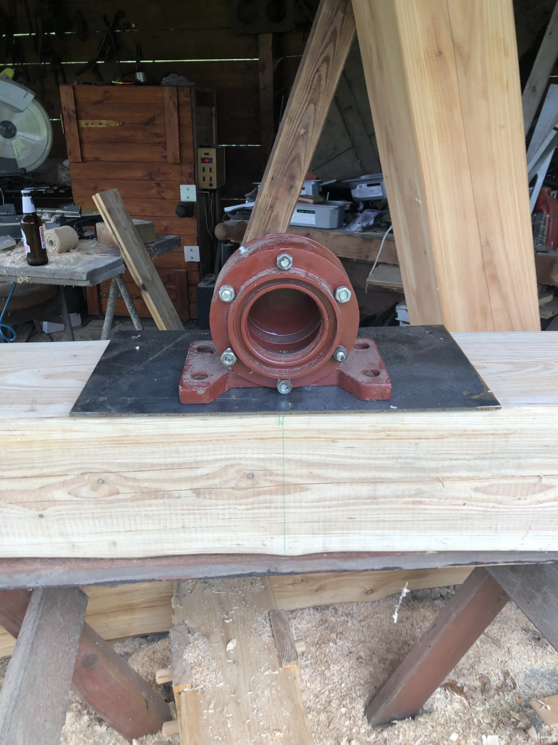
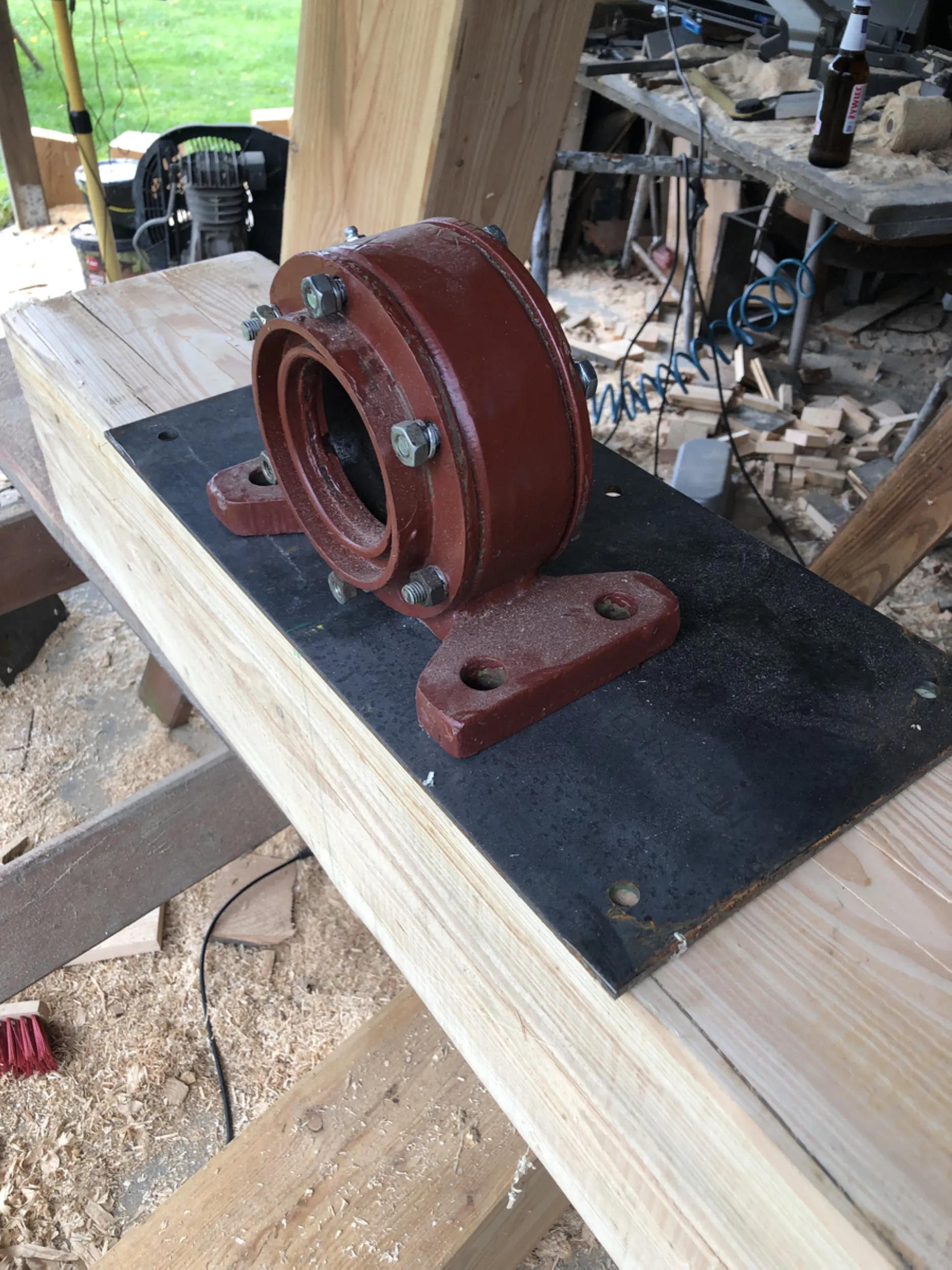
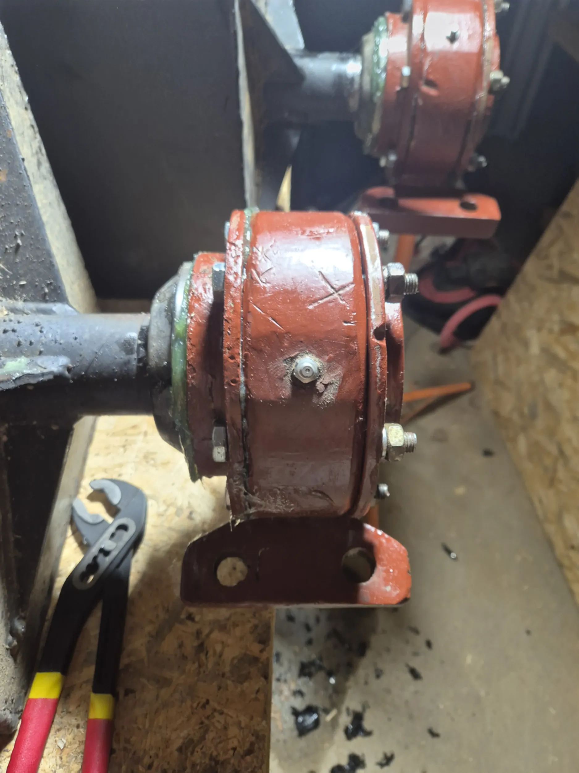
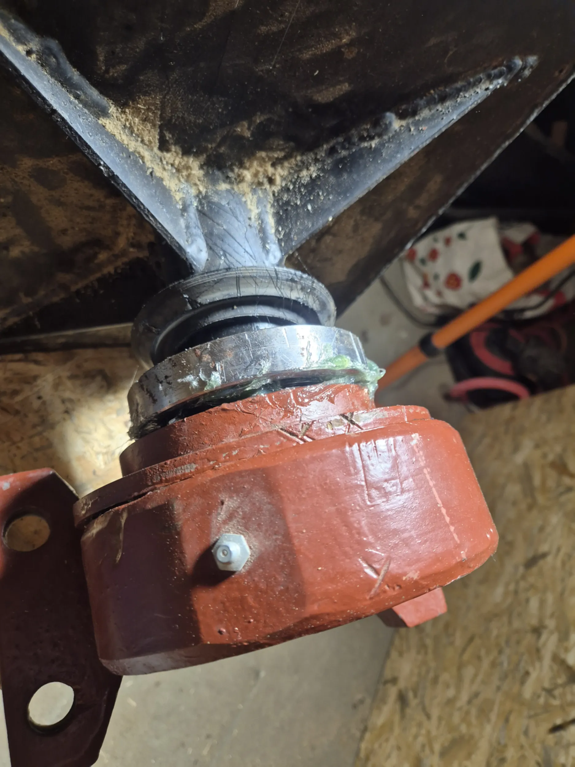
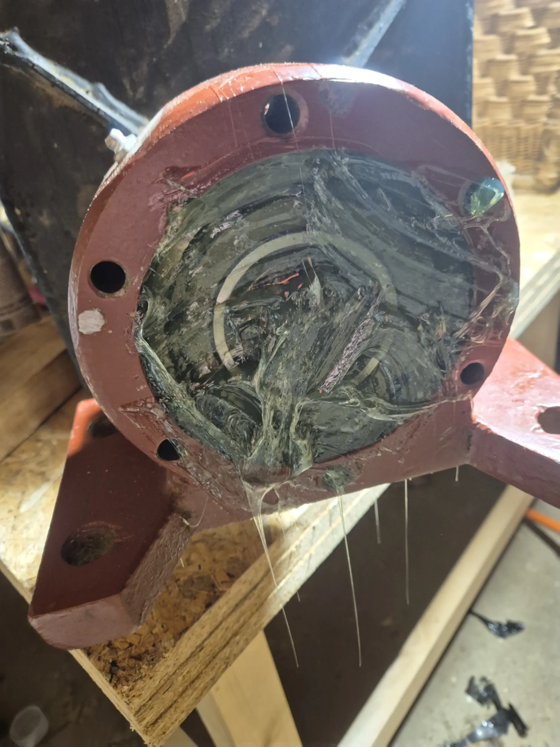
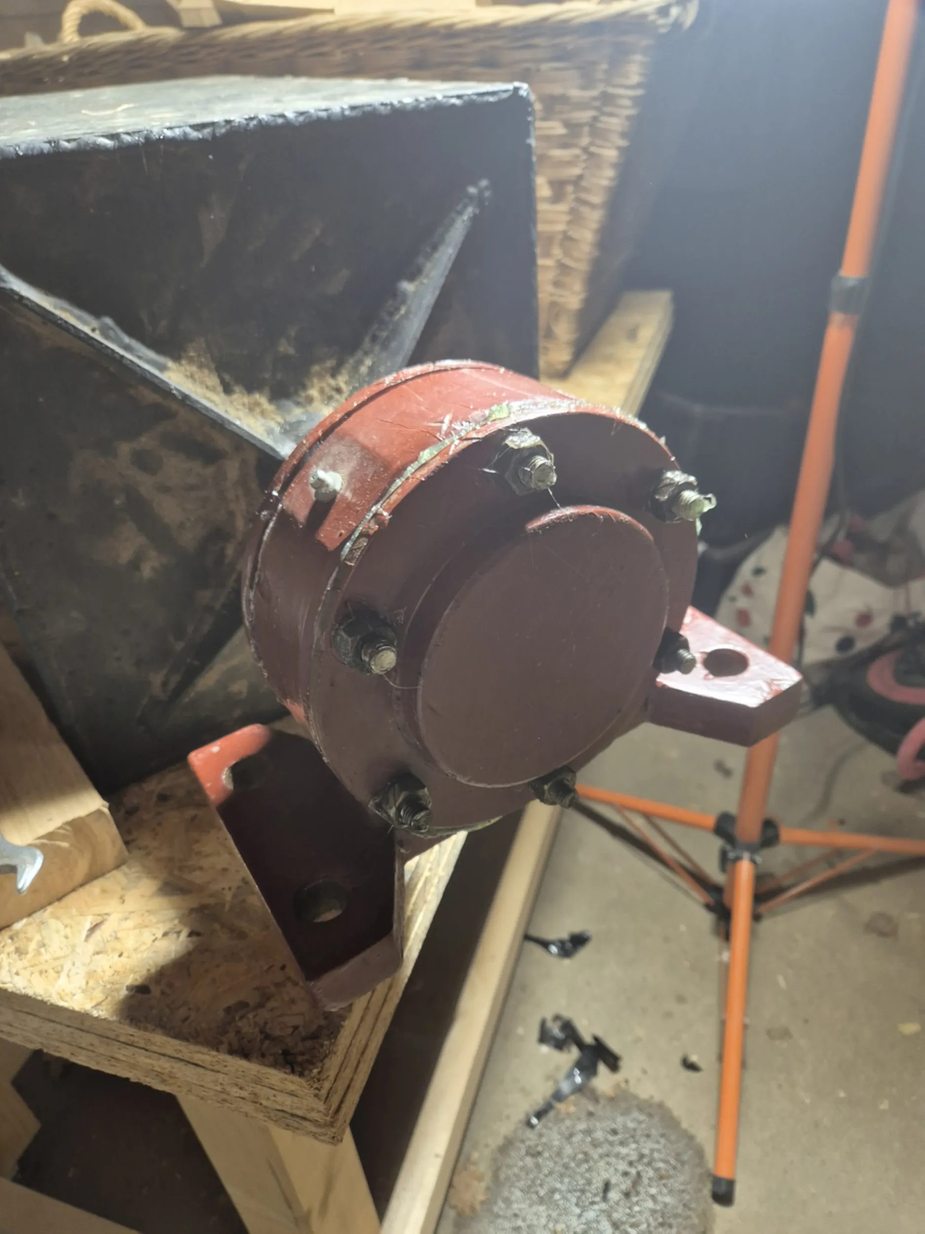
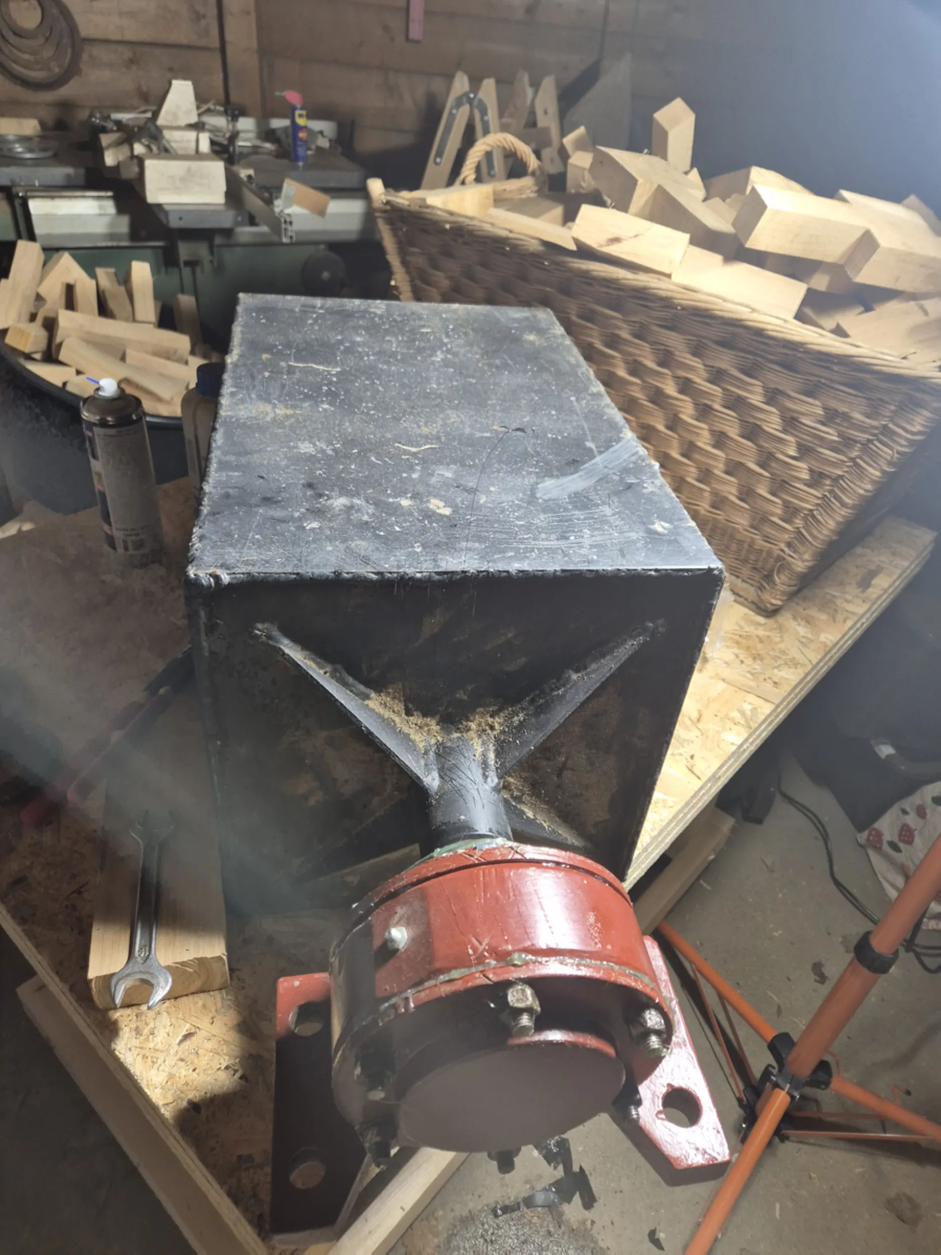
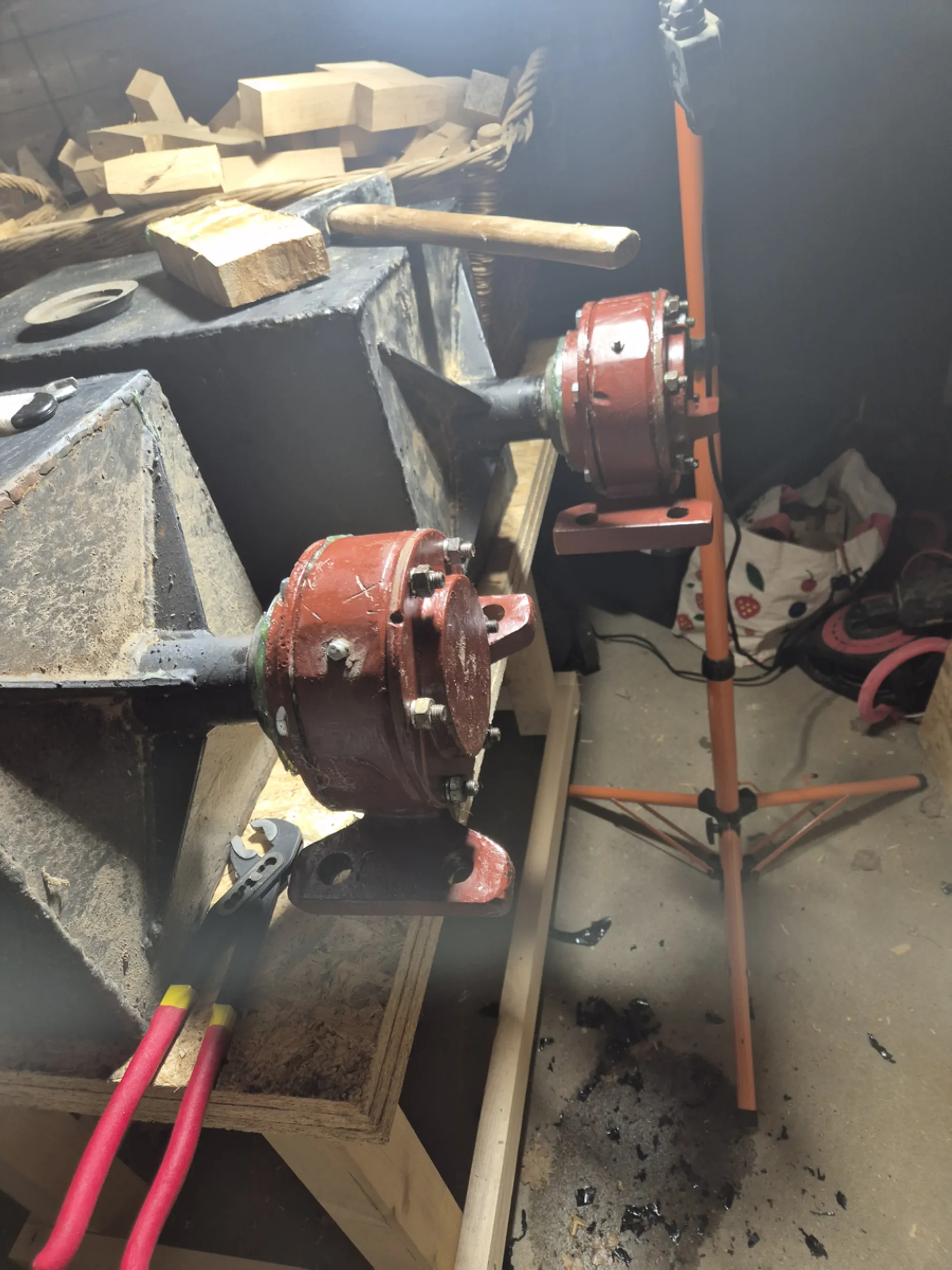
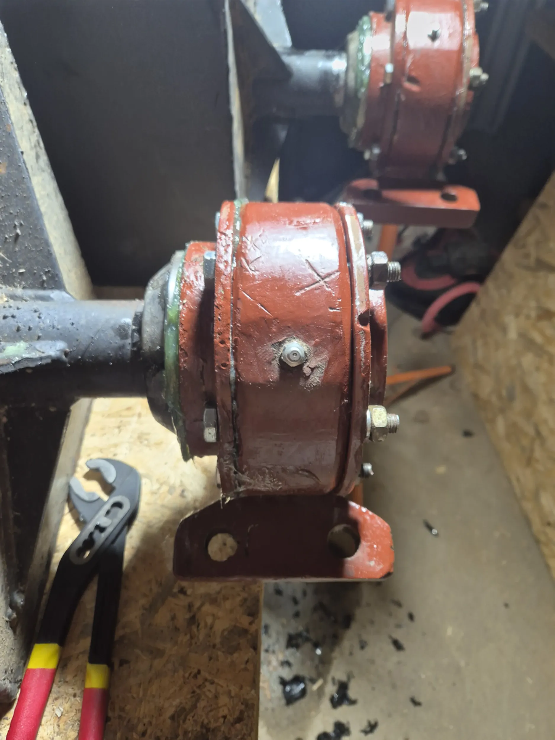
18 – Waterwheel Axle Bearings and Support
The efficient operation of a waterwheel requires proper support for its axle and ensures the smoothest possible movement of the entire structure. Work focused on preparing the bearing components, which bear the weight of the wheel and the loads generated during its operation.
A significant amount of time was devoted to fitting the mating surfaces, checking dimensions, and ensuring the coaxial alignment of the entire assembly. In structures of this type, even minor deviations could lead to increased resistance, accelerated wear, or uneven mechanism operation.
The solutions presented draw upon historical water-powered machinery, where durability and reliability depended on the quality of every detail. A properly prepared axle support is a key element in ensuring the safe and long-term operation of the waterwheel.
- rurmus project -
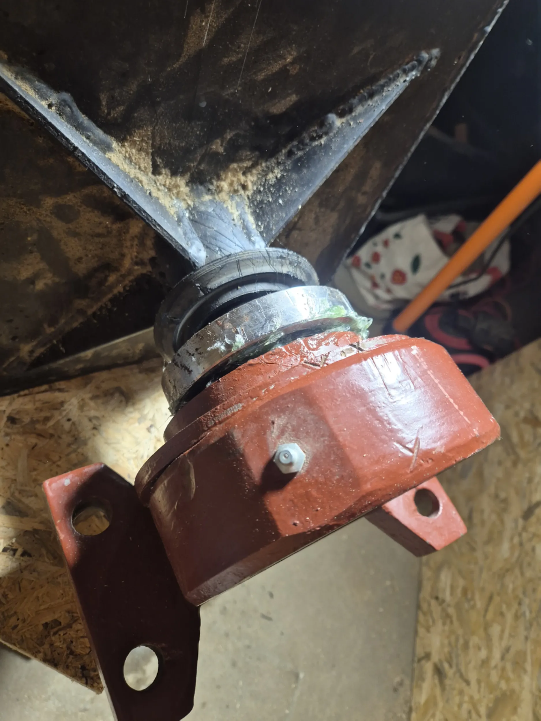
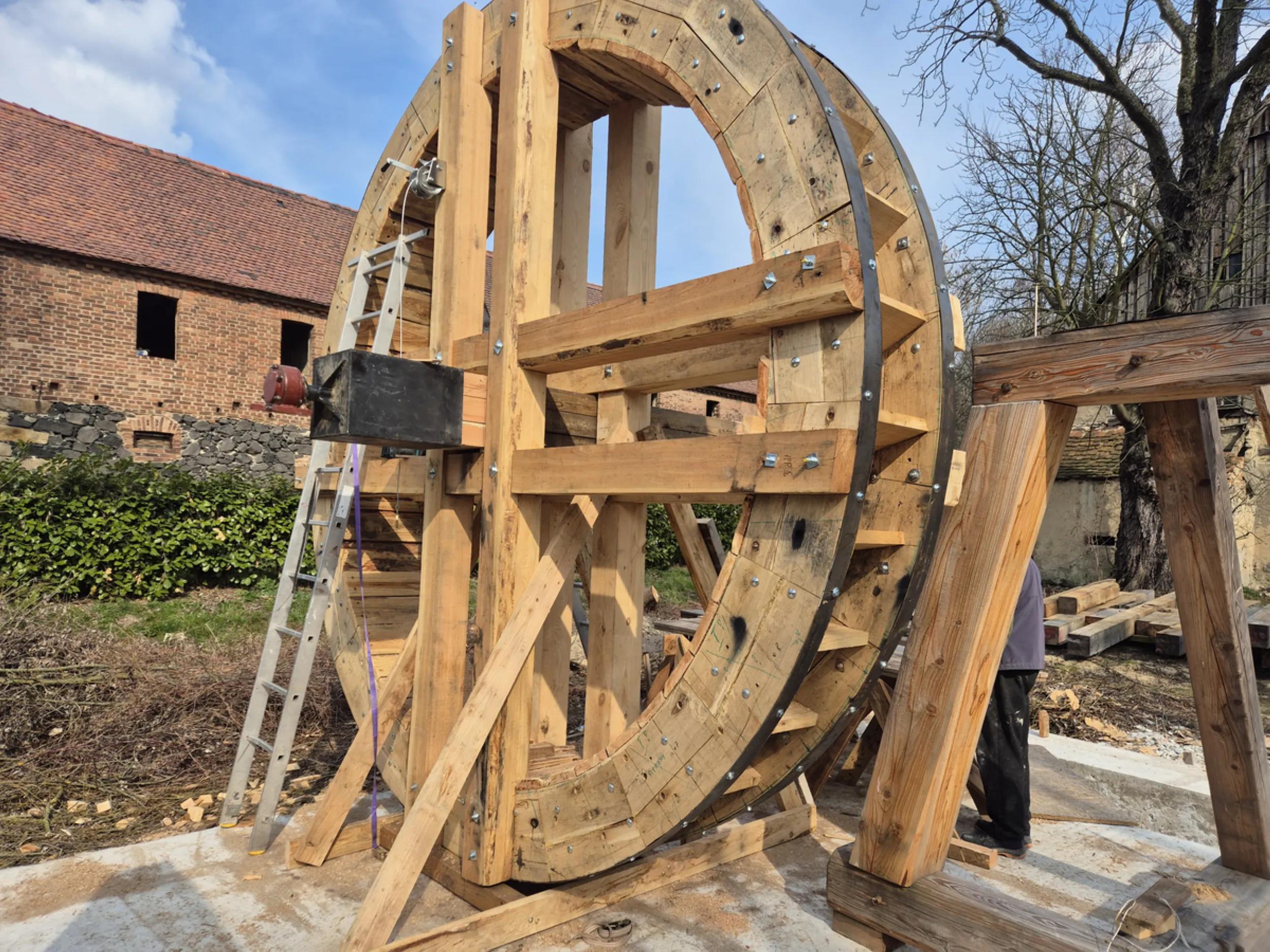
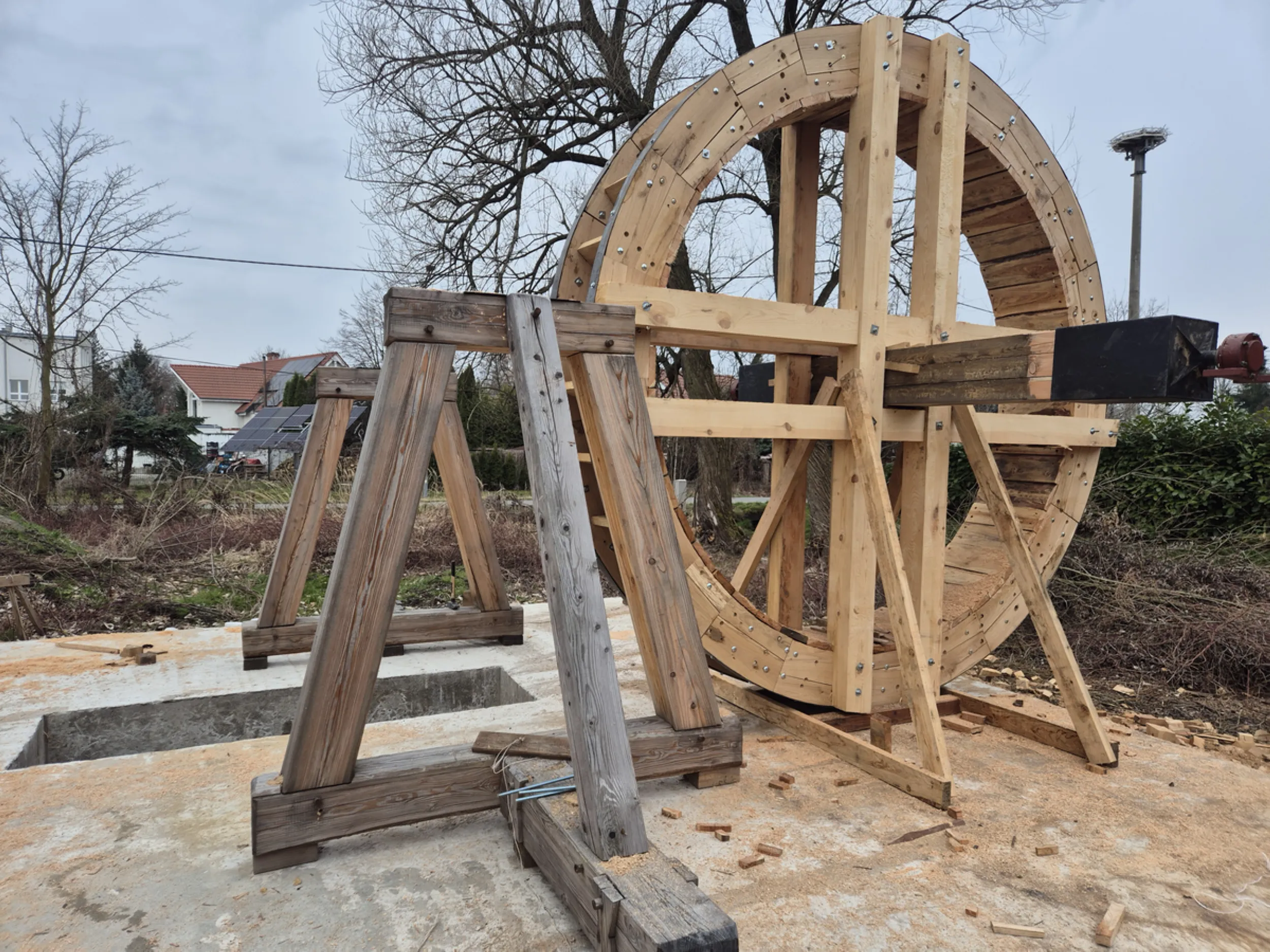
19 – Waterwheel axle bearings and sliding surfaces
Beyond the axle itself and its support structure, the components responsible for minimizing friction during the waterwheel’s operation play a crucial role. The work involved fitting the bearings, preparing the sliding surfaces, and verifying the interaction of all parts constituting the rotating assembly.
Each working surface required meticulous machining and fitting, as the smoothness of the entire structure’s movement depended on the precision of the workmanship. Maintaining appropriate operating clearances allowed the axle to rotate freely while safely bearing the significant loads generated during the device’s operation.
Solutions of this type were widely used in historic mills and water-powered machinery. The quality of the workmanship relied on the craftsman’s expertise and his ability to achieve proper contact between mating parts without the use of modern bearing systems.
- rurmus project -
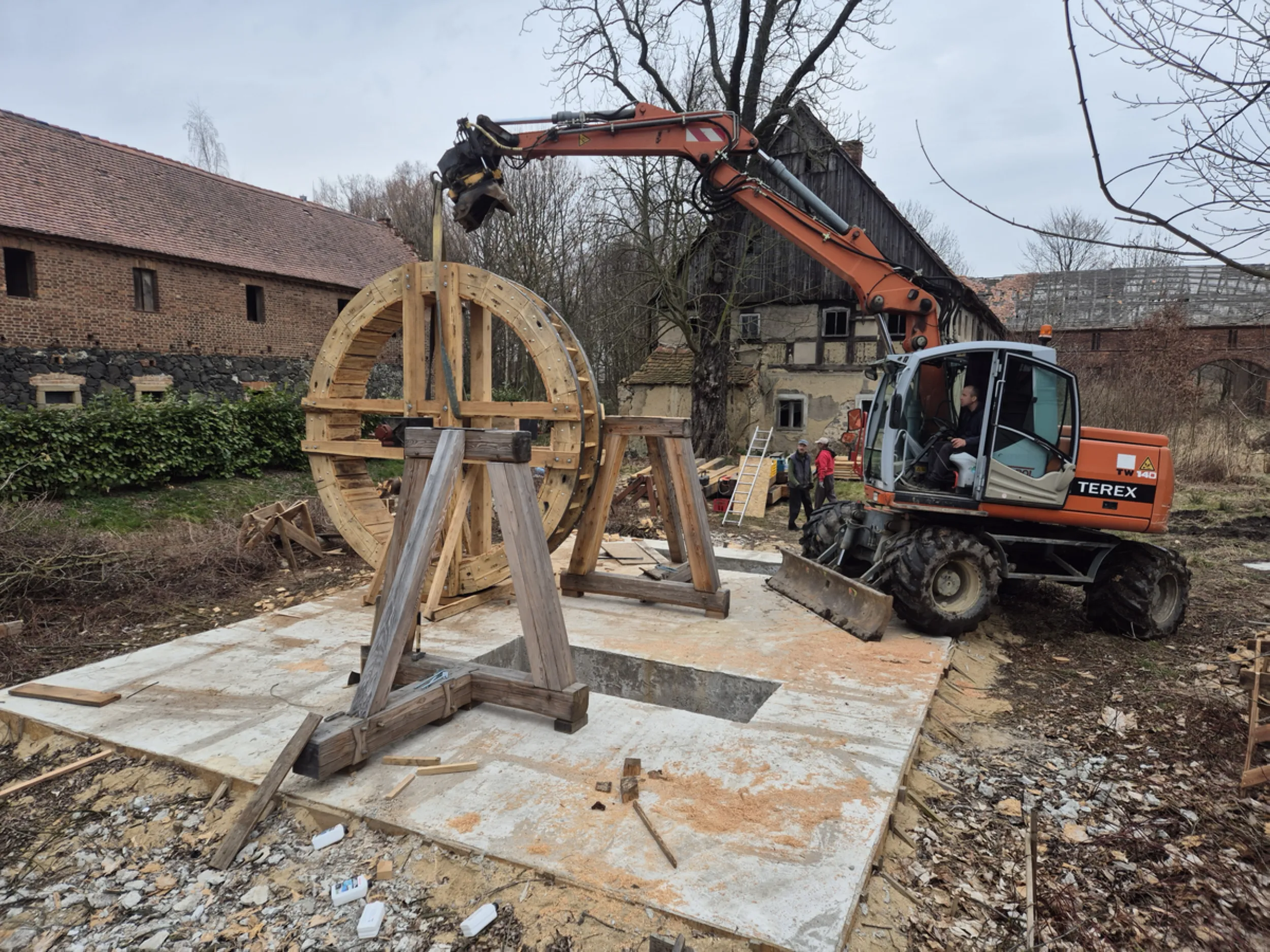
20 – Initial mounting of the water wheel onto the axle
The work shown here captures the moment the device’s largest components—the water wheel, the axle, and the support system—were joined together. This was a crucial test of the precision with which the preceding parts had been crafted, as the true geometry of the entire structure could only be assessed once they were assembled.
Great care was taken to ensure the system’s axial alignment, even weight distribution, and the smooth rotation of the wheel on its supports. The structure’s massive dimensions required cautious maneuvering and repeated checks of how the individual components were positioned relative to one another.
This is the stage where individual parts cease to be mere workshop components and begin to form a functioning mechanical assembly. It is at this point that the proportions, scale, and operational dynamics of the future Rurmus drive mechanism can be evaluated for the first time.
- rurmus project -
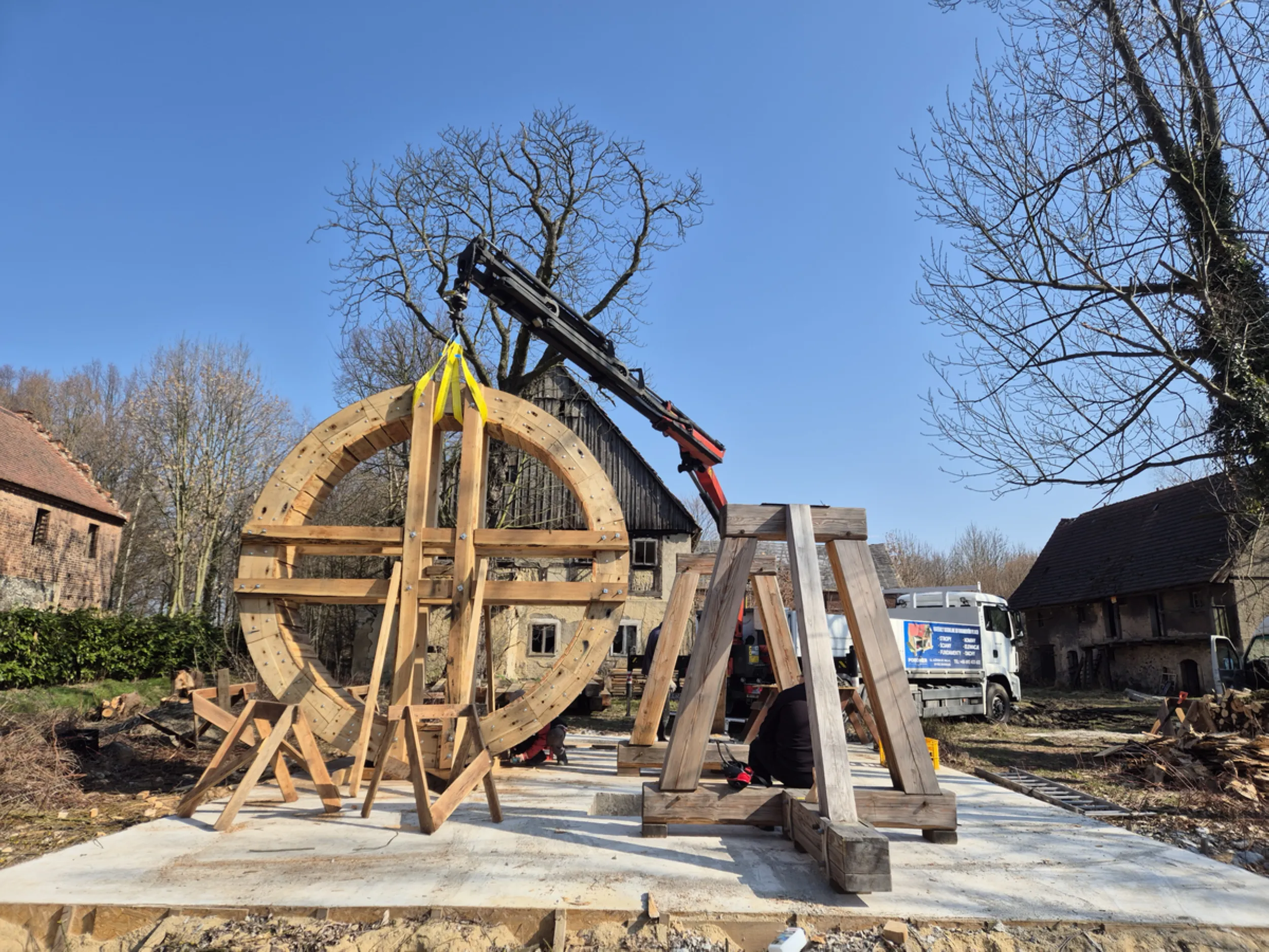
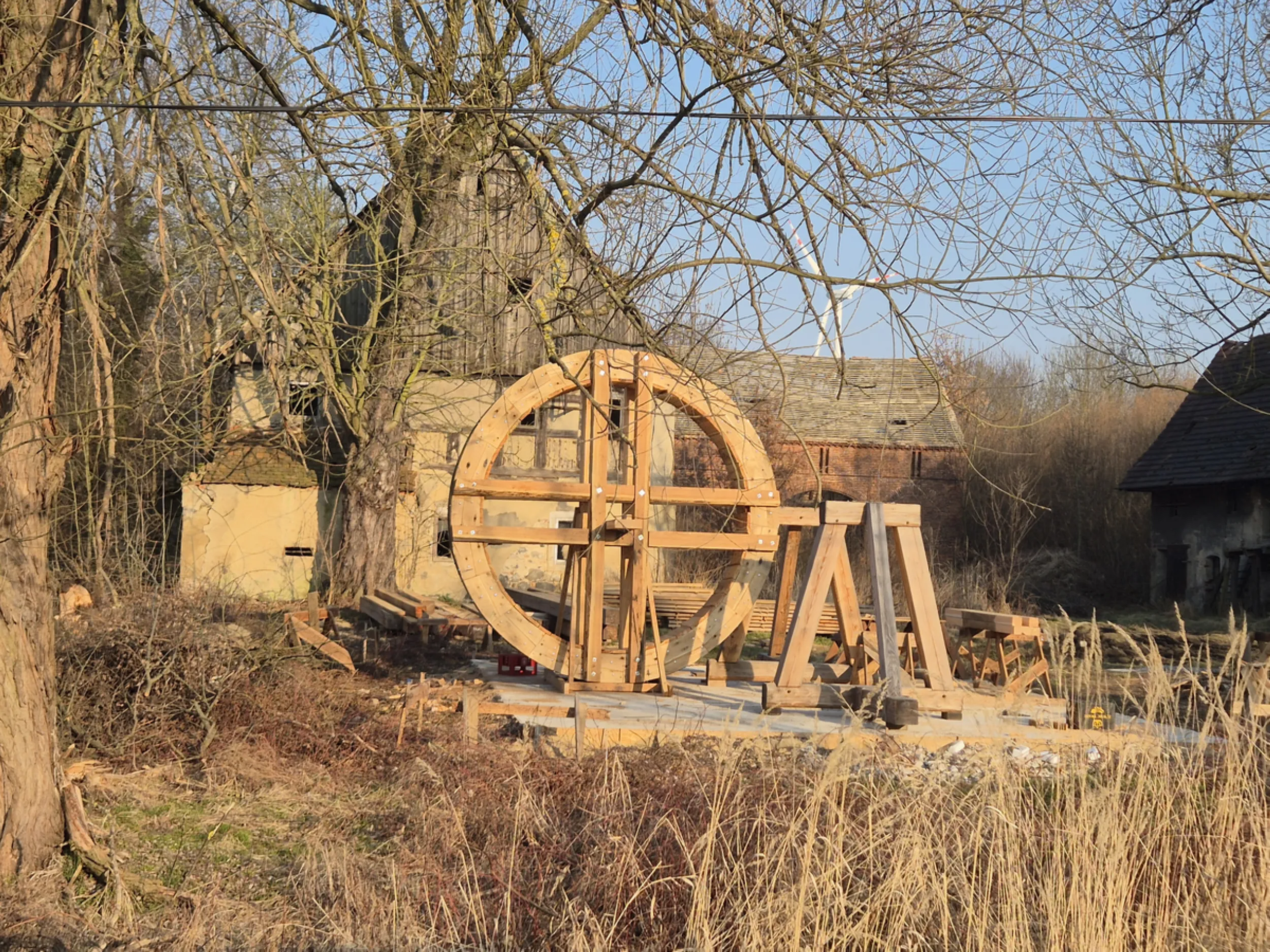
21 – Water wheel in operating position
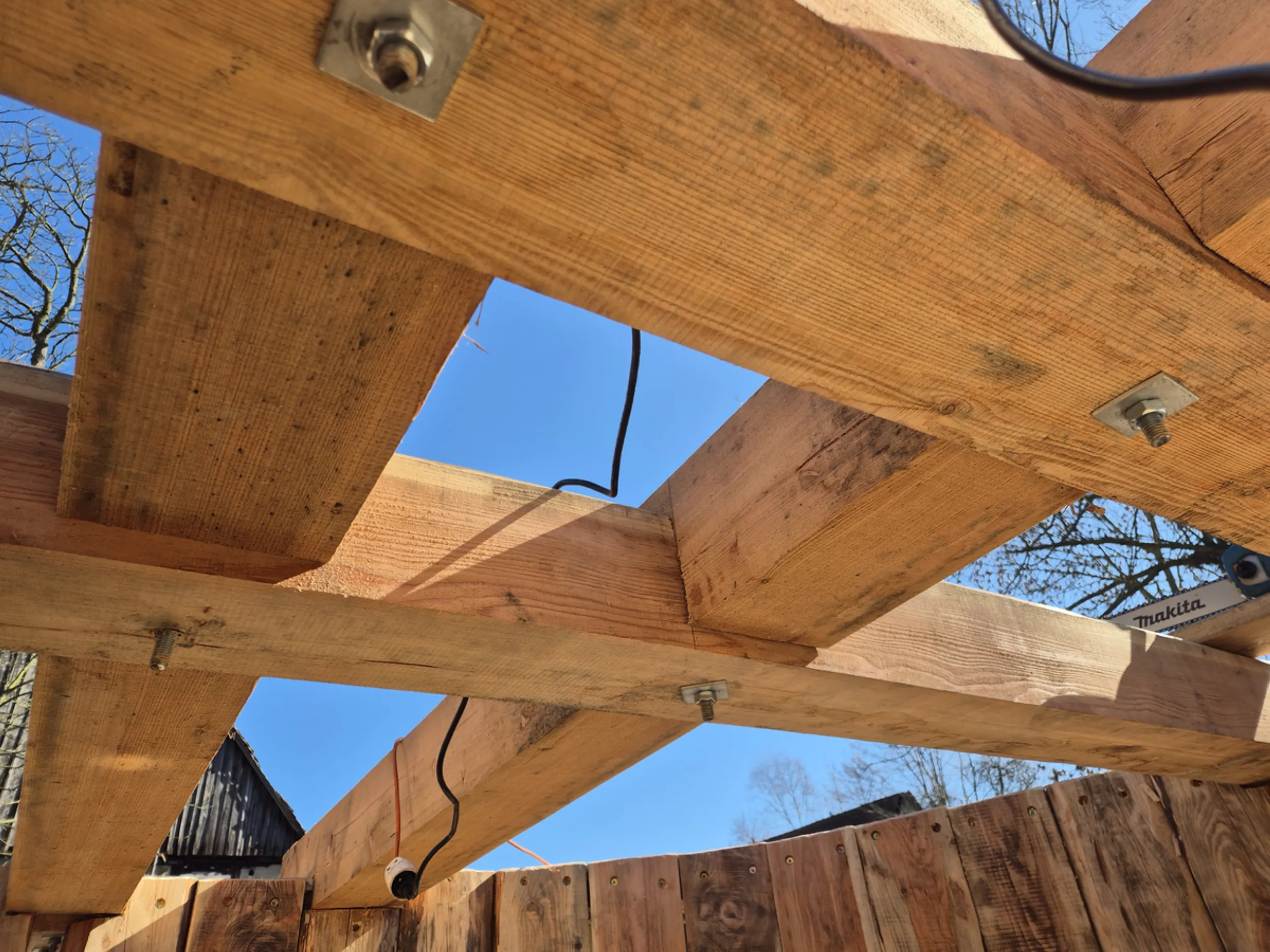
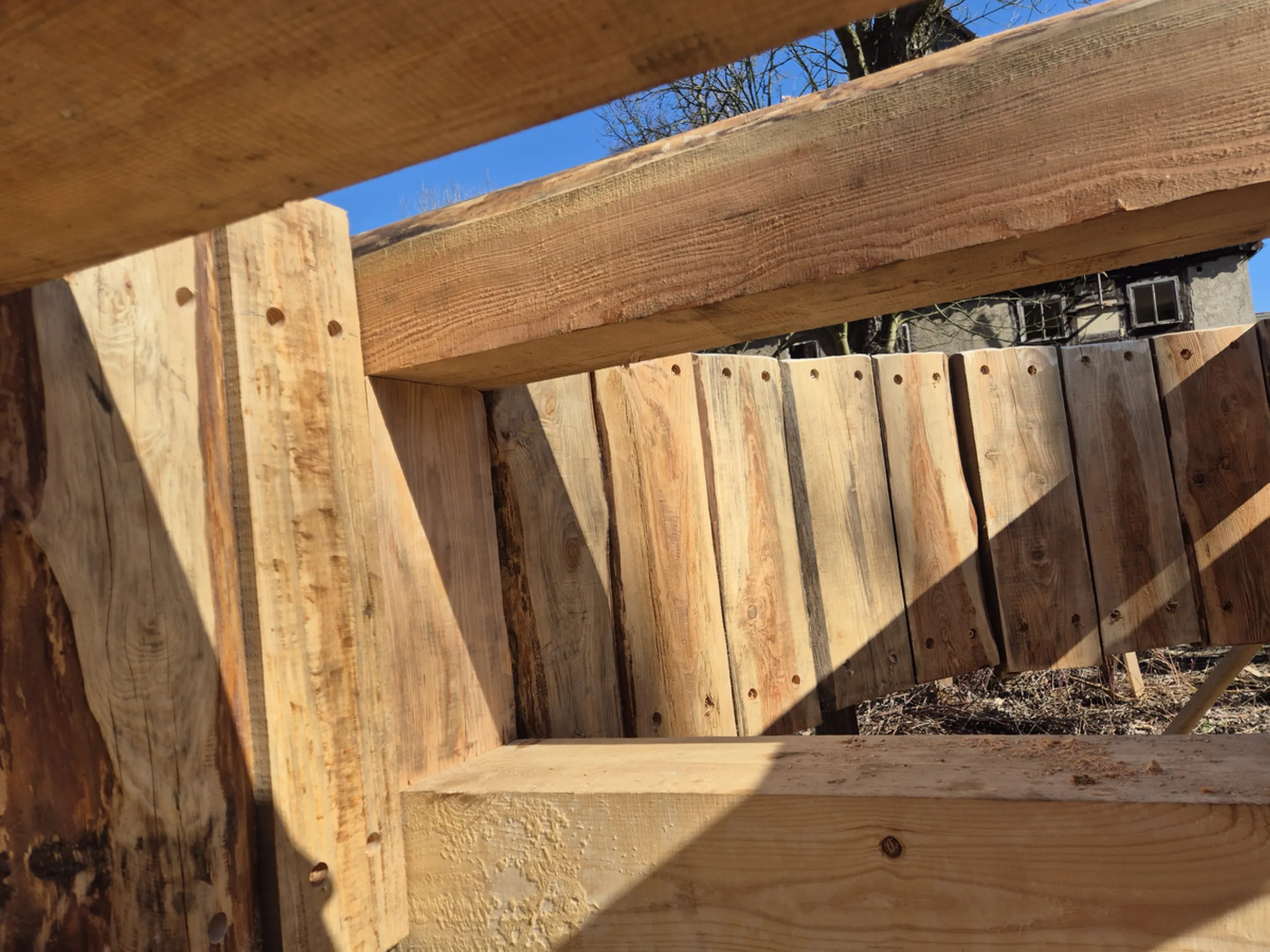
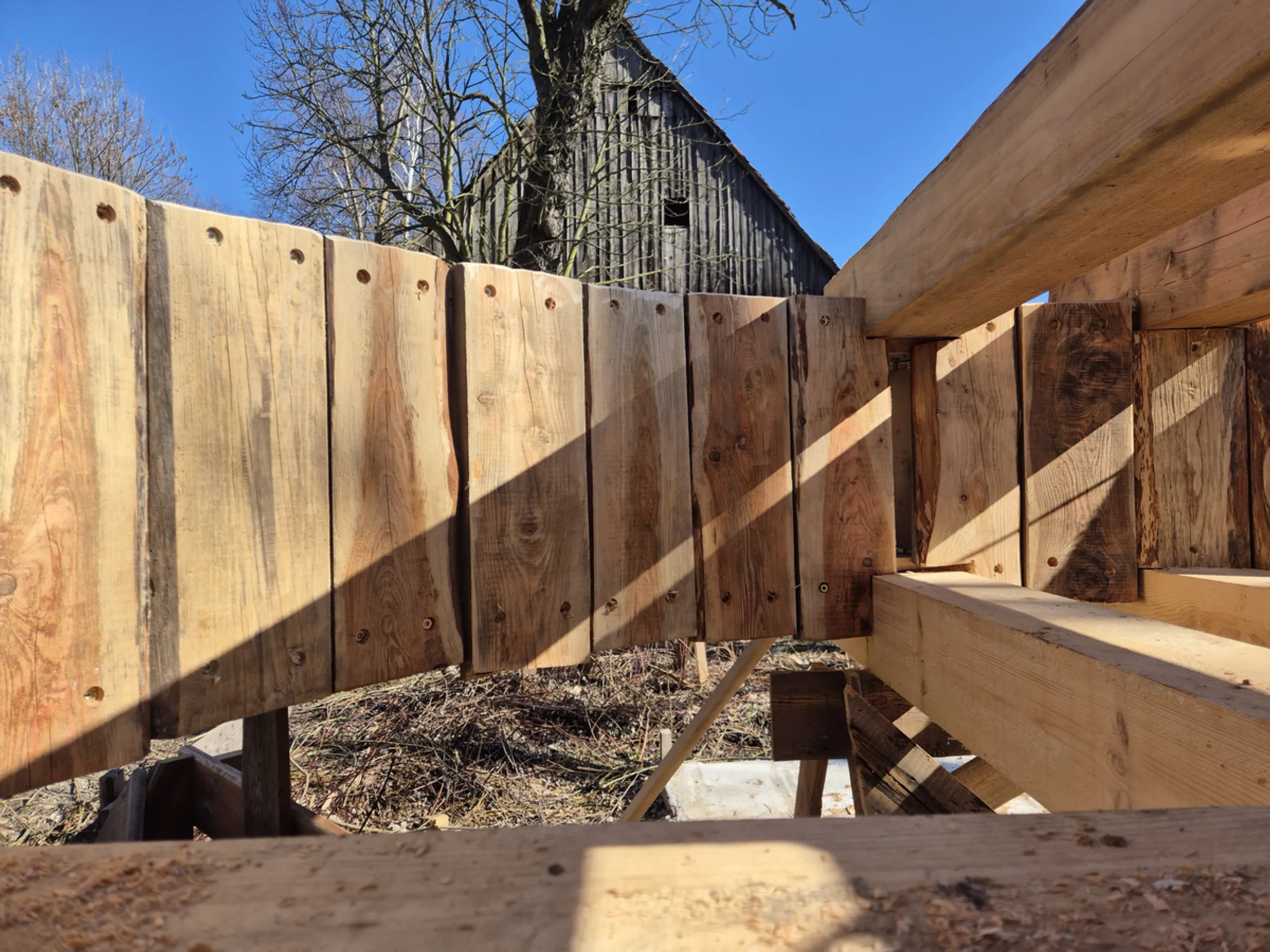
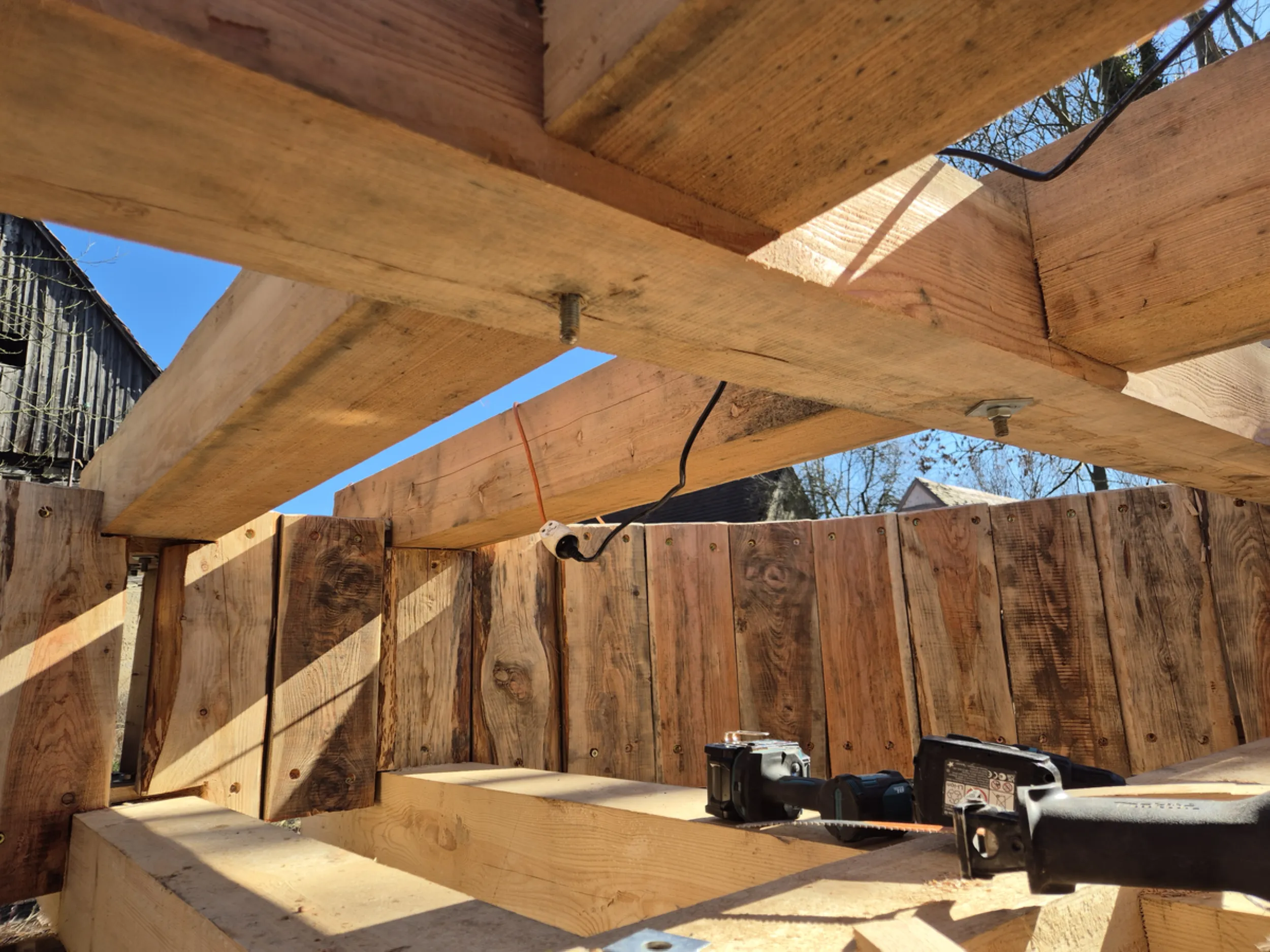
The water wheel has reached a position close to its final operating location, allowing for an assessment of how it interfaces with the Rurmus structure. Visible are the support elements, the main axle, and the load-bearing system responsible for handling the significant loads generated during the device’s operation.
A crucial part of the work involved verifying the alignment of the wheel, the axle, and the support structure. Maintaining the correct clearances, levels, and overall system geometry was vital, as the mechanism’s future efficiency and durability depend on these parameters.
This is the moment when the true scale of the project becomes apparent. The Rurmus’s main drive component is taking its place within the structure and beginning to form an integrated system with the rest of the device.
- rurmus project -
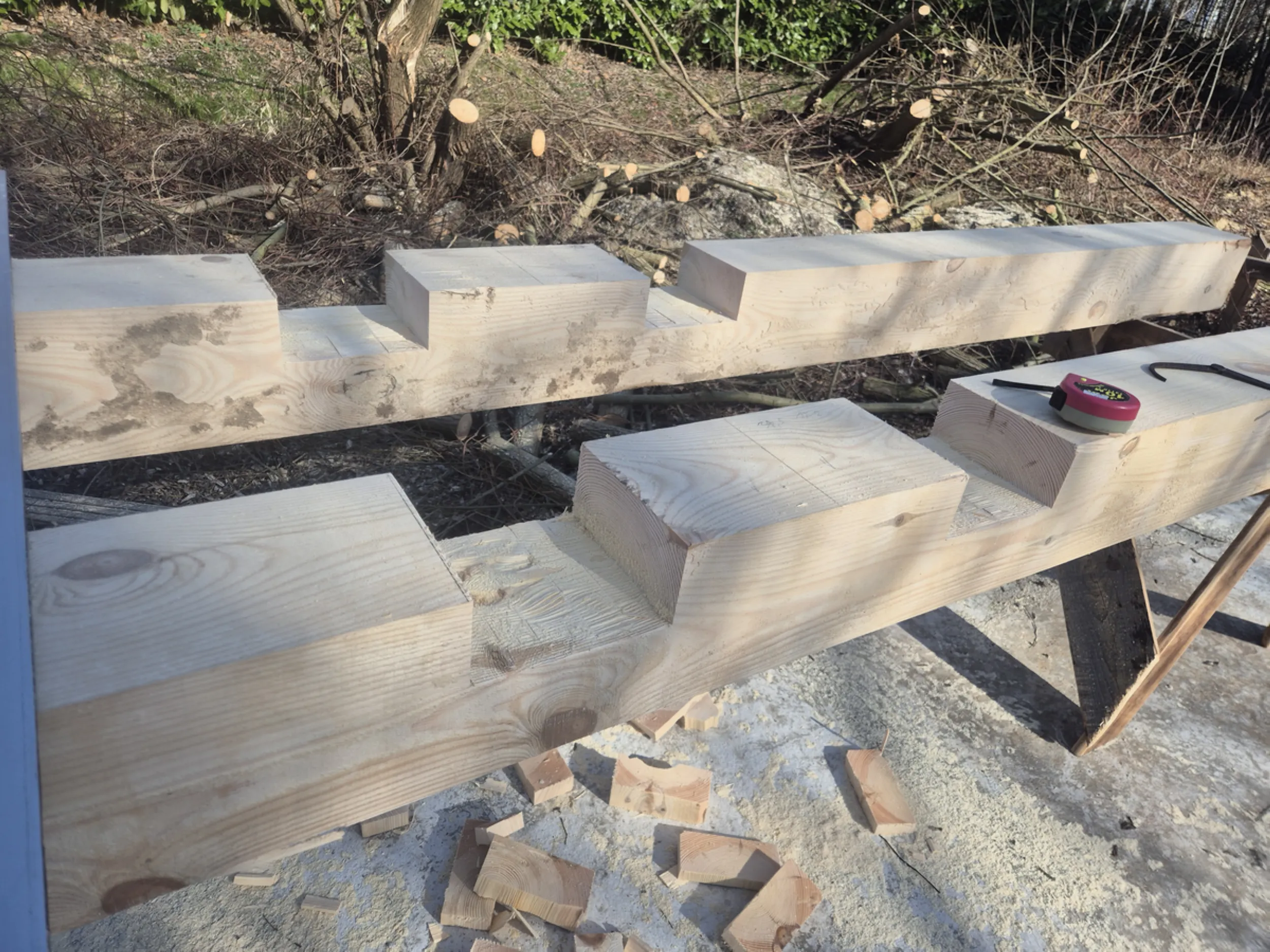
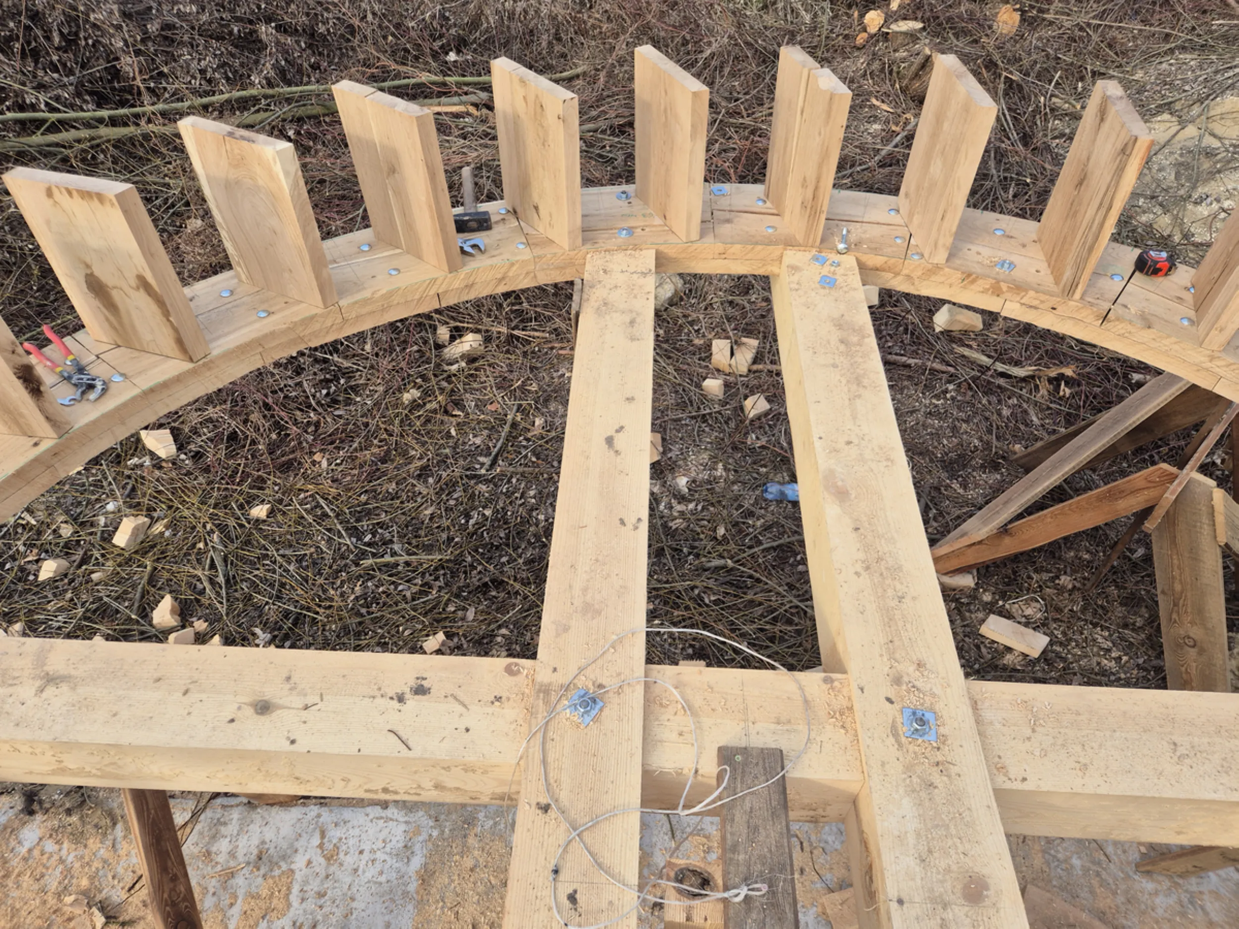
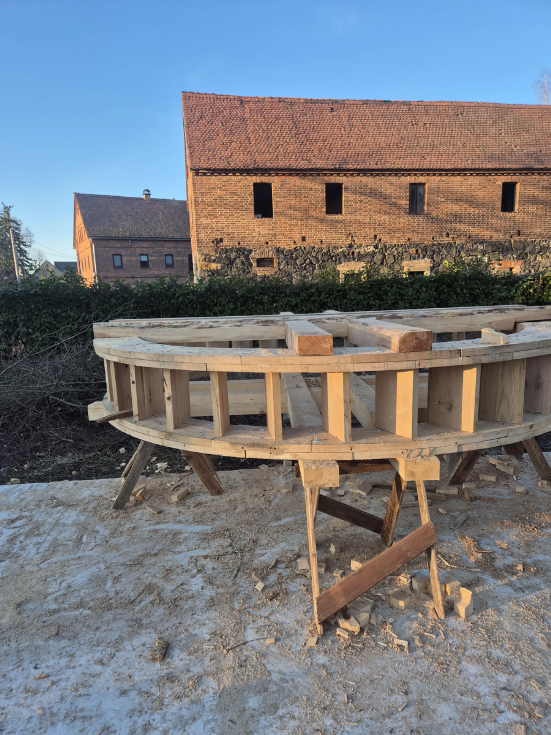
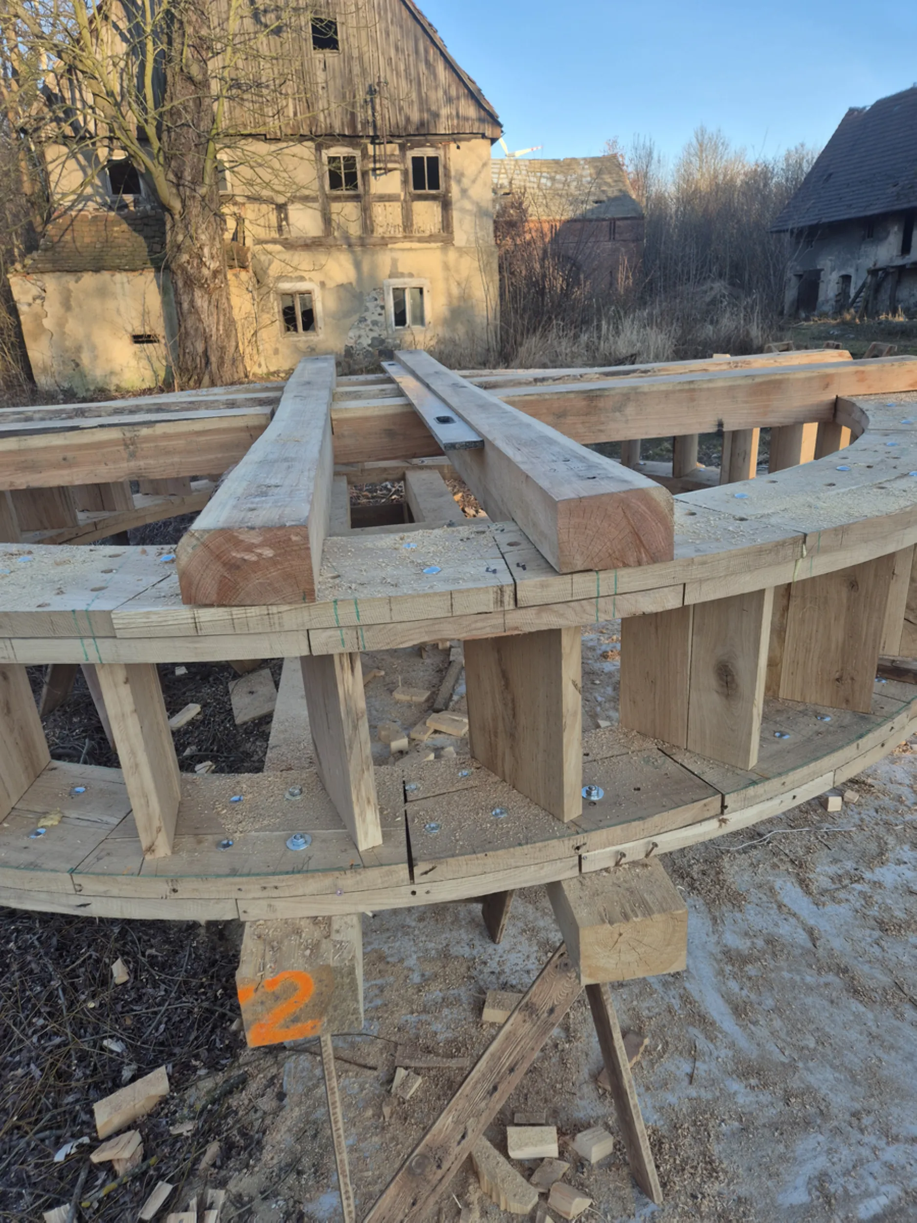
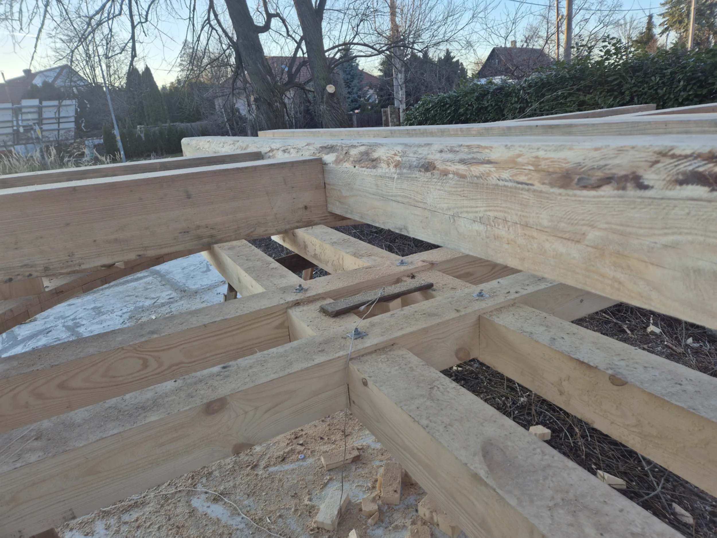
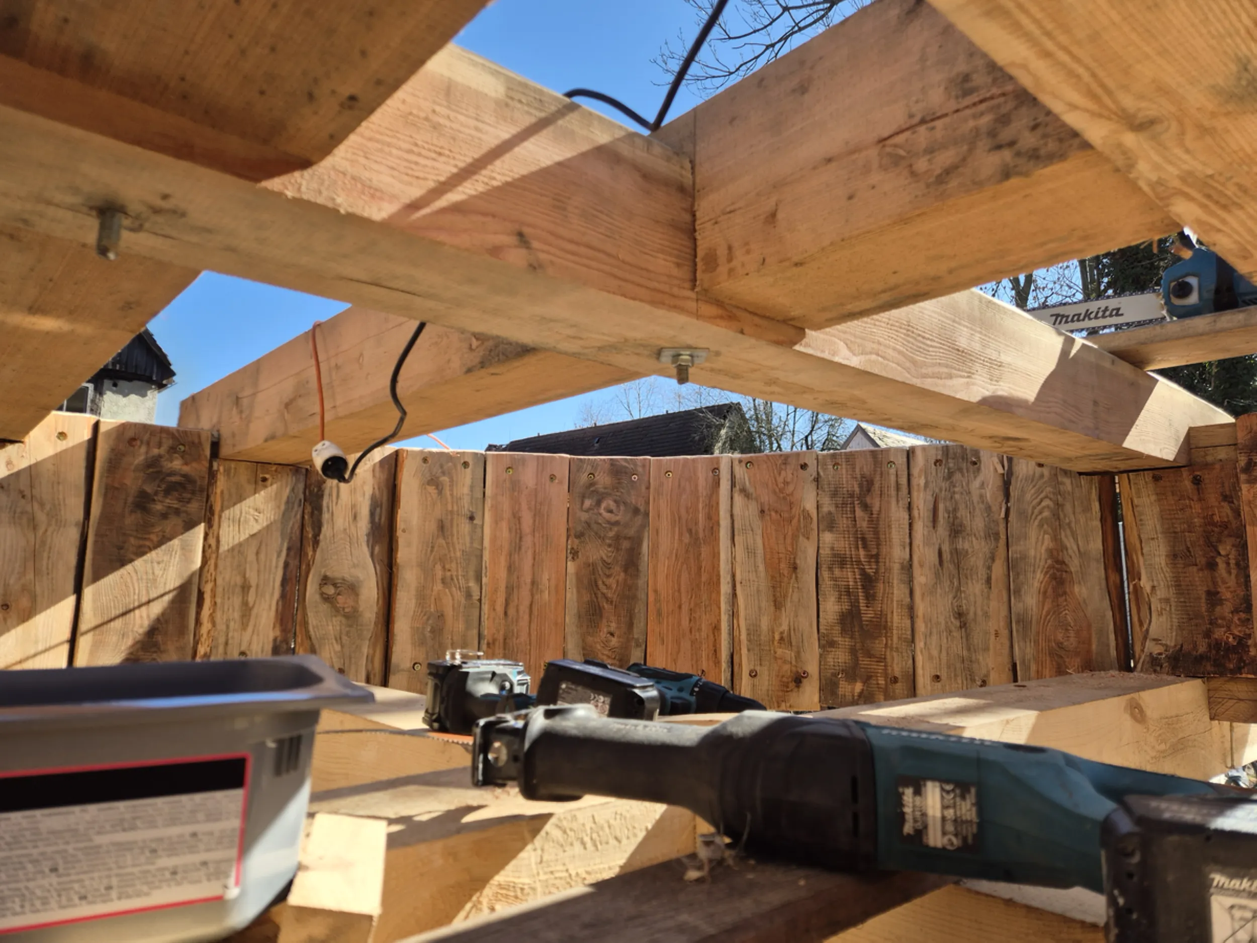
22 – Internal Structure of the Water Wheel
A water wheel is more than just the rim and water-catching buckets visible from the outside. Equally important is its internal structure, which transfers loads between the axle and the outer part of the wheel. This section reveals the primary load-bearing elements that form the framework of the entire structure, as well as the system of connections ensuring its rigidity and durability.
Precision in fitting the joints and maintaining the symmetry of the entire assembly was crucial during the fabrication of these components. Every beam and connection point had to work in concert with the rest of the structure to enable the wheel to safely support its own weight and withstand the forces generated during operation.
It is here that the carpentry aspect of the water wheel’s construction is most evident. The internal arrangement of beams, joints, and bracing creates a structure that—while virtually invisible once assembly is complete—determines the strength and integrity of the entire device.
- rurmus project -
23 – Water Wheel Support Cross
One of the most critical structural elements of the water wheel is the internal support cross that connects the wheel’s central hub to its outer rim. This assembly bears a significant portion of the loads generated during the device’s operation and ensures the structural integrity and proper geometry of the entire unit.
The work involved fitting massive beams, constructing the joints, and assembling them into a single, rigid framework. Maintaining symmetry was of particular importance, as even minor discrepancies could affect the wheel’s balance and smooth operation.
Although the support cross acts as a hidden internal skeleton, its importance is comparable to that of a building’s foundation. It enables the safe transfer of forces between the axle, spokes, and rim, ensuring the wheel maintains the necessary rigidity despite its substantial size and weight.
- Education - Folklore - Culture -
Contact us—we have the knowledge, experience, and international connections.
Together, we will develop and implement your idea.